6 Function & parameter description
Group 4 – I/O setup
Lenze · Inverter i510 / i550 - Cabinet · Operation Manual · 0.4 EN · 02/2016 75
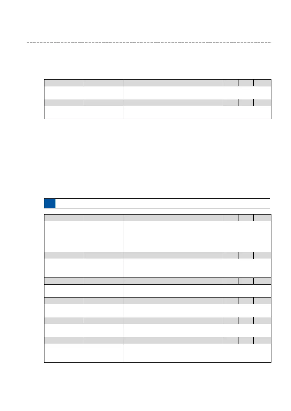
6.6.4 User defined faults
Two user defined fault can be configured. (Example: To stop motor in case of process fault) If a user defined fault
occurs the inverter goes into fault state. After clearing the fault the resetting of the inverter is required.
0:Not connected
(Reference see P400:1)
Configuration of user defined fault 1
0:Not connected
(Reference see P400:1)
Configuration of user defined fault 2
6.6.5 Digital input configuration
The digital input are used for control operations. The following configurations are available for the digital input
signals:
Assertion Level (Only I550)
The I550 digital inputs can be used with PNP or NPN signals. The setting applies for all digital inputs!
Signal inversion
Every digital Input can be inverted individually
Connection list / Function
In general a digital input is assigned to a specific function like Start Reverse or Quick stop. With that it is pos-
sible to have more than one function on the same digital input.
See chapter 6.6.1 Function list (Run/Stop/Start/Jog/Reverse), page 69 for the configurable functions.
0: LOW active
1: HIGH active
Input signal assertion for PNP/NPN selection
0: Low
For NPN input signals
1: High
For PNP input signals
0: Digital input
1: Encoder (AB) (*)
Mode selection for digital input functionalities (DI4 / DI3):
0: DI4 / DI3 = digital inputs
1: Encoder (AB)
0: Not inverted
1: Inverted
Inversion of Digital Input
0: Not inverted
1: Inverted
Inversion of Digital Input
0: Not inverted
1: Inverted
Inversion of Digital Input
0: Not inverted
1: Inverted
Inversion of Digital Input

 Loading...


