6 Function & parameter description
Group 3 – Motor control
Lenze · Inverter i510 / i550 - Cabinet · Operation Manual · 0.4 EN · 02/2016 67
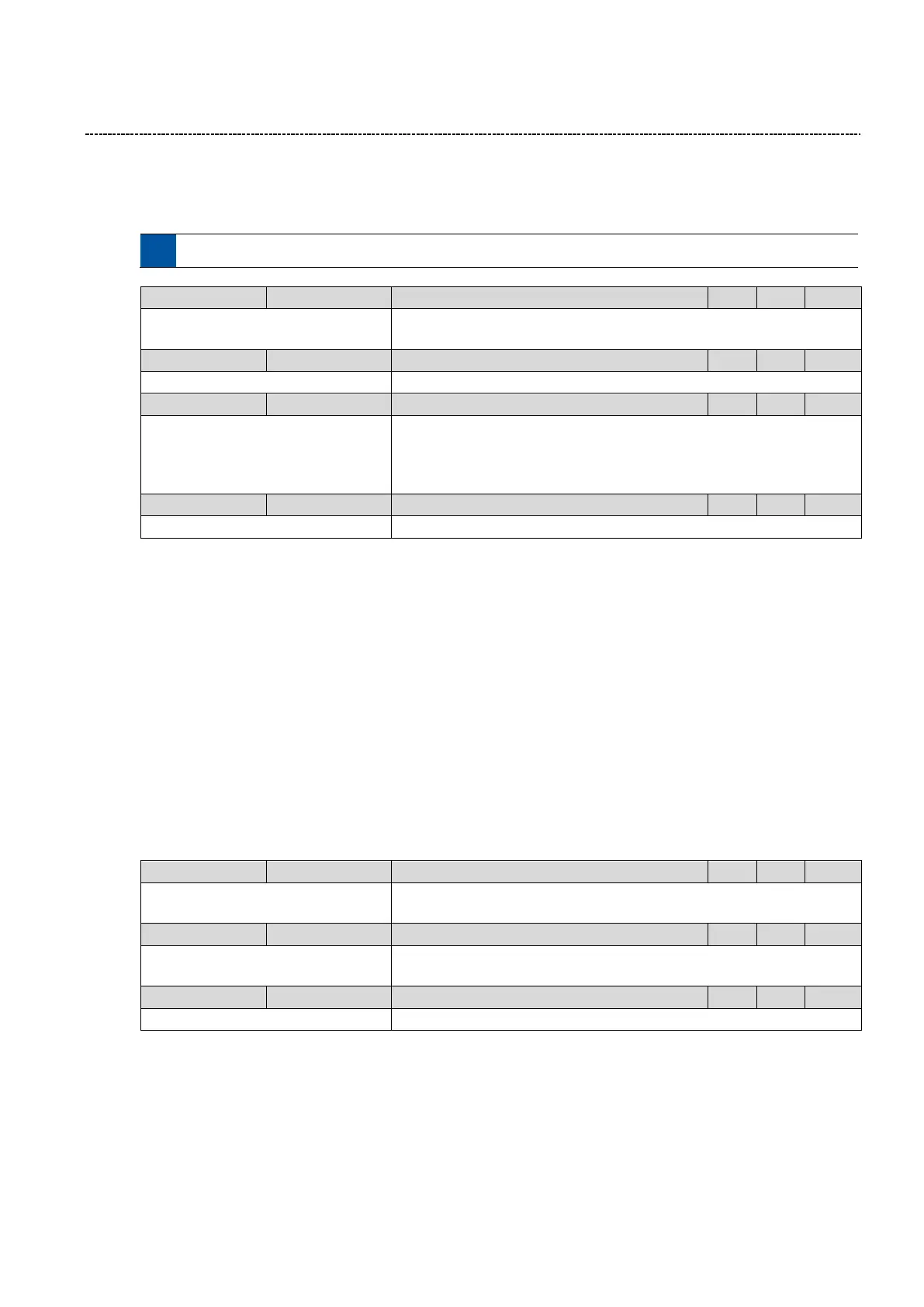
6.5.15 Torque limitation
The maximum torque can be limited.
Note: The limitation is not active in V/f mode!
0.001 ... [Type Code dependent] ...
1000.000 Nm
Motor rated torque in [Nm]
0.0 ... [250.0] ... 3000.0 %
Maximum motor torque in % of P325:0
0: No reaction
1: Warning
2: Trouble
3: Fault
Torque limitation fault reaction
Note: Status bit "MotorTorqueMax" is set independently of the selected
response.
Torque monit:Shutter delay
0.000 ... [0.000] ... 10.000 s
Torque limitation fault delay
6.5.16 HTL Encoder setup
A HTL encoder can be connected to the DI3 and DI4 of the inverter. The encoder can be used for:
As a motor encoder for speed control
As a process encoder as a setpoint (e.g. true web speed for winding application) or as an actual value for e.g.
PID Controller
Setup:
1. Select the encoder in P410:2
2. Set the encoder increment/revolution P341:1
3. Select the function of the encoder:
P600:2 Feedback PID / P201:2 PID setpoint / P201:1 Frequency setpoint
Note: If SC or SLPSM mode is selected the encoder is automatically assigned as feedback.
The actual encoder feedback is displayed in 0x2C42:6
Set the number of increments per revolution of the connected encoder
(See data sheet of the encoder)
0: Digital input
1: Encoder (AB) (*)
Mode selection for digital input functionalities (DI4 / DI3)
-- ... [Actual value] ... -- rpm
Actual velocity feedback of encoder

 Loading...


