6 Function & parameter description
Group 5 – Fieldbus
Lenze · Inverter i510 / i550 - Cabinet · Operation Manual · 0.4 EN · 02/2016 83
6.7 Group 5 – Fieldbus
See chapter 7 Fieldbus on page 95
6.8 Group 6 – PID setup
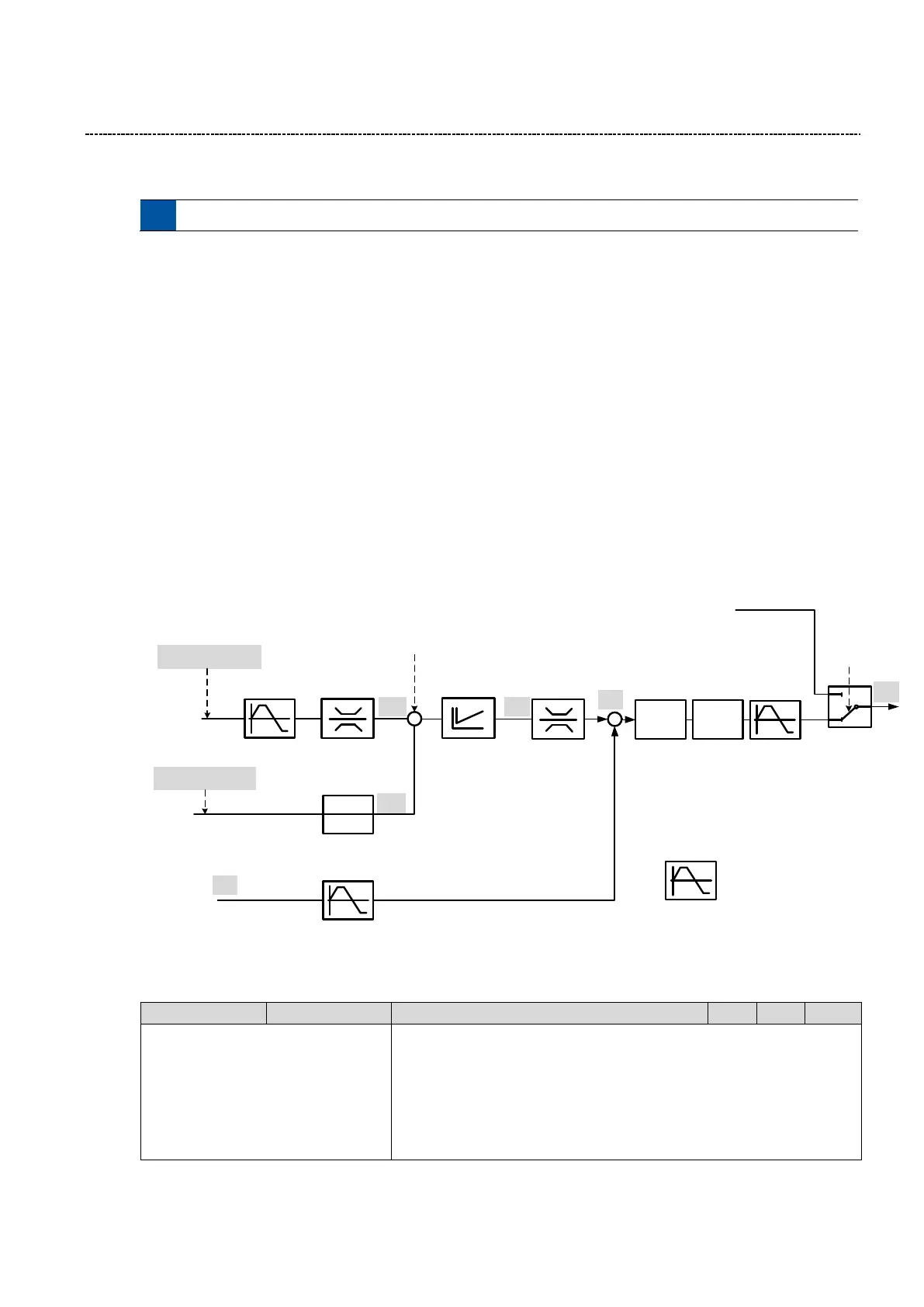
To regulate the motor speed related to a process value the inverter has a PID controller integrated. This is a
closed loop control.
Example:
Using an feedback signal (i.e. pressure transducer) the inverter can regulate the speed.
Setup procedure:
1. Select the correct PID Operating mode (P600:1)
2. Select the PID feedback source (P600:2) and setup the analog input accordingly
3. Select the PID default setpoint source (P201:2)
4. Set the PID speed range (P600:3) to a proper value
5. Test and tune your PID control
(Start with default settings first)
6. Set additional functions (if needed)
Setpoint ramp time, PID ramp time, Min/Max Alarm, line speed, influence function.
PID Default setpoint source
P201:2 (0x2860:2)
Setoint limits (PID)
P605:2 (0x404E:2)[PUnit]
P605:1 (0x404E:1) [PUnit]
PID Setting
P: P601:0 (0x4048:0)[%]
I: P602:0 (0x4049:0)[ms]
D: P603:0 (0x404A:0)[s]
PID Feedback source
P600:2 (0x4020:2)
Setpoint ramp (PID)
P604:0 (0x404B:0) [s]
PID alarm
P608:1 (0x404D:1) [Punit]
P608:2 (0x404D:1) [Punit]
PID Speed forward source
P600:4 (0x4020:4)
PID Acc/Dec
P606:2 (0x4021:2)[s]
P606:1 (0x4021:2)[s]
Standard Ramps
PID Operating mode
P600:1(0x4020:1)
PID
>?
<?
Controlled speed range
P600:3 (0x4020:3)
PID influence ramp
Influence ramps active: P400:48 (0x2631:48)
Ramp up time: P607:1 (0x404C:1)
Ramp down time: P607:2 (0x404C:2)
PID integrator disabled
P400:47 (0x2631:47)
PID output forced to 0
400:46 (0x2631:46)
PID off (Trigger)
P400:45 = FALSE
(0x2631:45)
1
0
+
Hz
Hz
PUnit
PUnit Hz
SPEED SETPOINT
Hz
Actual PID setpoint
P121:1 (0x401F:1) [PUnit]
Actual PID Feedback
P121:2 (0x401F:2) [PUnit]
Sleep
Rinse
Jog
Stop
6.8.1 PID Setup
0: Disabled
1: Normal operation
2: Reverse operation
3: Normal bi-drectional
4: Reverse bi-directional
PID Operating mode
0: Disabled:
PID is disabled
1: Normal operation
Direct acting system. Motor needs to increase the speed to increase the

 Loading...


