4 Installation
Electrical installation
Lenze · Inverter i510 / i550 - Cabinet · Operation Manual · 0.4 EN · 02/2016 21
4.2.4 Default control setup
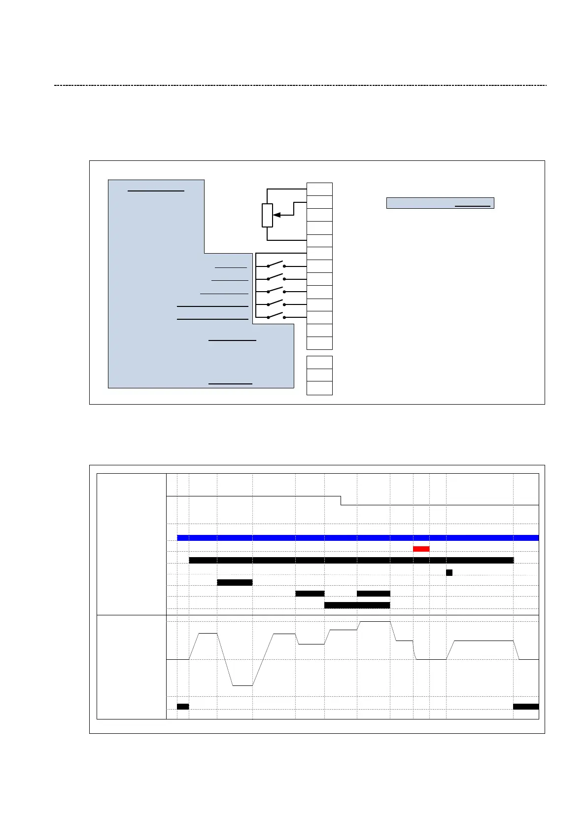
The i5x0 has a default I/O preconfiguration intended for many typical applications. This preconfiguration is de-
scribed below (i510 pictured):
GND
AO1
AI2
AI1
DI1
24V
10V
DI5
DI4
DI3
DI2
GND
DO1
Run/Stop
Preset selection bit 1
Preset selection bit 0
Control I/O Terminals
Reset fault
Invert rotation
Earth Ground for Analog and Digital Signals
Analog Input 1 (P430:1 DEFAULT: 0...10 VDC )
Analog Input 2
Analog Output 1
10 VDC Supply for Potentiometer
24 VDC, 100 mA Supply, Reference for Digital Inputs
Programmable Digital Input 1
Programmable Digital Input 2
Programmable Digital Input 3
Programmable Digital Input 4
Programmable Digital Input 5
Programmable Digital Output 1
Earth Ground for Analog and Digital Signals
P400:2
P400:19
P400:18
P400:4
P400:13
NO
Relay Common
COM
Relay Normally Open
NC
Relay Normally Closed
Relay set to Energize on
“Ready to run” condition
P420:1
DO1 set to Energize on
“Release brake” condition
P420:2
P201:1
(configures AI1 as the
default setpoint source)
1k … 10k
Potentiometer
Preconfiguration
Fig. 7: i510, I/O preconfiguration
The i5x0 inverter can be operated “out-of-the-box” with this control scheme and without any further configura-
tion. Below is an example of the inverter behavior based on the default signals described above:
50Hz*
-
-
-
-
0Hz
35Hz
25Hz
AI1 Value
Mains (VAC)
FAULT condition
Run/Stop DI1
Reset fault DI2
Invert rotation DI3
Preset sel. bit0 DI4
Preset sel. bit1 DI5
Ready to run (Relay)
35Hz
-35Hz
20Hz
(Preset 1)
40Hz
(Preset 2)
25Hz
25Hz
Signal InputsOutputs
Motor Speed
50Hz*
(Preset 3)
50Hz*
-
-
-
-
0Hz
-
-
-
-
-50Hz*
35Hz
*Default values 50Hz/60Hz are depending on the Type Code!
Fig. 8: Control scheme

 Loading...


