6 Function & parameter description
Group 2 – Basic setup
54 Lenze · Inverter i510 / i550 - Cabinet · Operation Manual · 0.4 EN · 02/2016
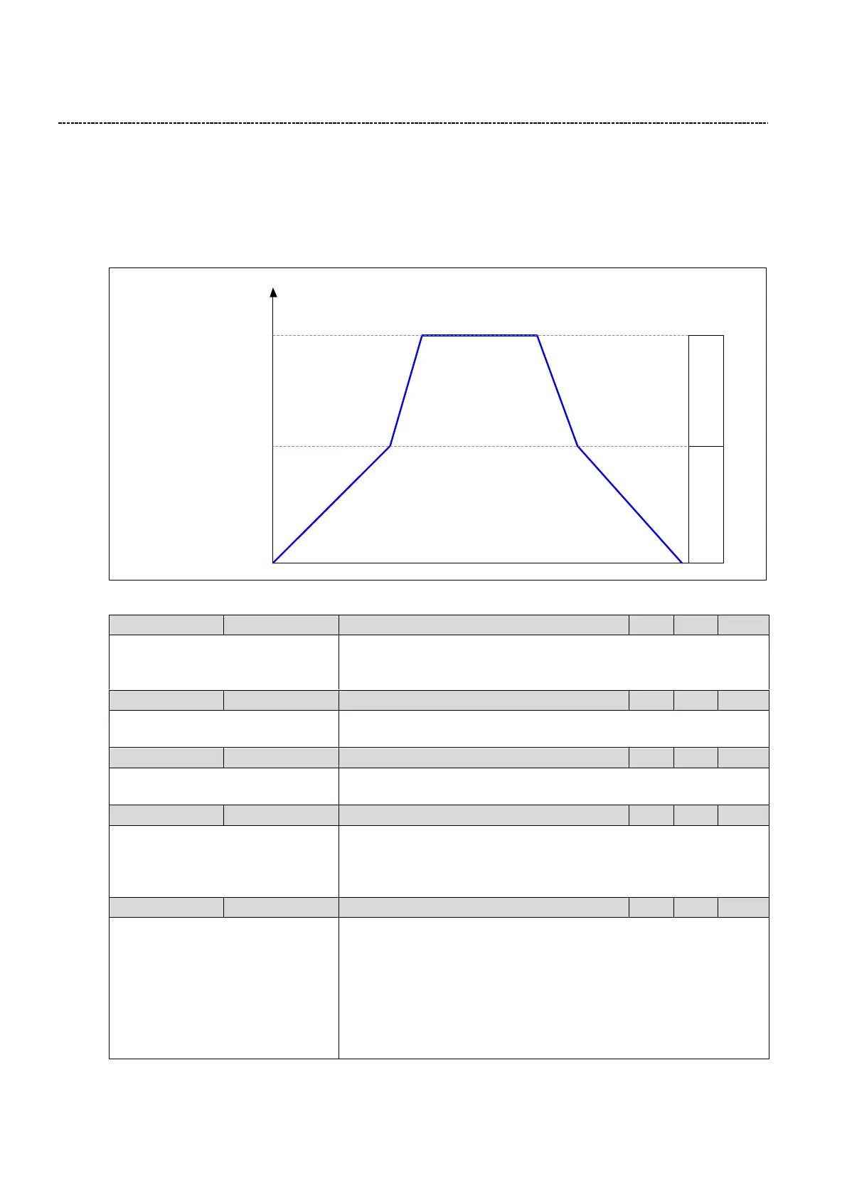
6.4.8 Acceleration / Deceleration
Two sets of Acceleration/Deceleration ramps are available. Two ways of switching between ACC/DEC 1 and
ACC/DEC 2 are available:
External Trigger (i.e. Digital Input)
Ramp time switch level to trigger from ACC/DEC1 tp ACC/DEC2 based on Frequency
Minimum frequency
(P210:0)
Maximum frequency
(P211:0)
P
222
:
0
P
223
:
0
P
220
:
0
P
221
:
0
Ramp time switch level
(P224:0)
Accel/Decel 1
Range
Accel/Decel 2
Range
[Hz]
Fig. 17: Speed setpoint
0:Not connected
(Reference see P400:1)
Trigger for ACC/DEC2 selection:
TRUE: Selects ACC2/DEC2 as ramp times
0.0 ... [5.0] ... 3600.0 s
Acceleration time 1 for the output frequency to increase from 0.0 Hz to
Maximum frequency (P211:0)
0.0 ... [5.0] ... 3600.0 s
Deceleration time 1 for the output frequency to decrease from P211:0
Maximum Frequency to 0.0 Hz
0.0 ... [5.0] ... 3600.0 s
Acceleration time 2 for the output frequency to increase from 0.0 Hz to
Maximum frequency (P211:0)
Note: MOP use ACC/DEC2
0.0 ... [5.0] ... 3600.0 s
Acceleration time 2 for the output frequency to decrease from Maxi-
mum Frequency (P211:0) to 0.0 Hz
Note: MOP use ACC/DEC2

 Loading...


