Single−axis controllers
Wiring
Devices in the range 145 ... 245 A (75 ... 130 kW)
3
127
EDS94SPP101 EN 10.2
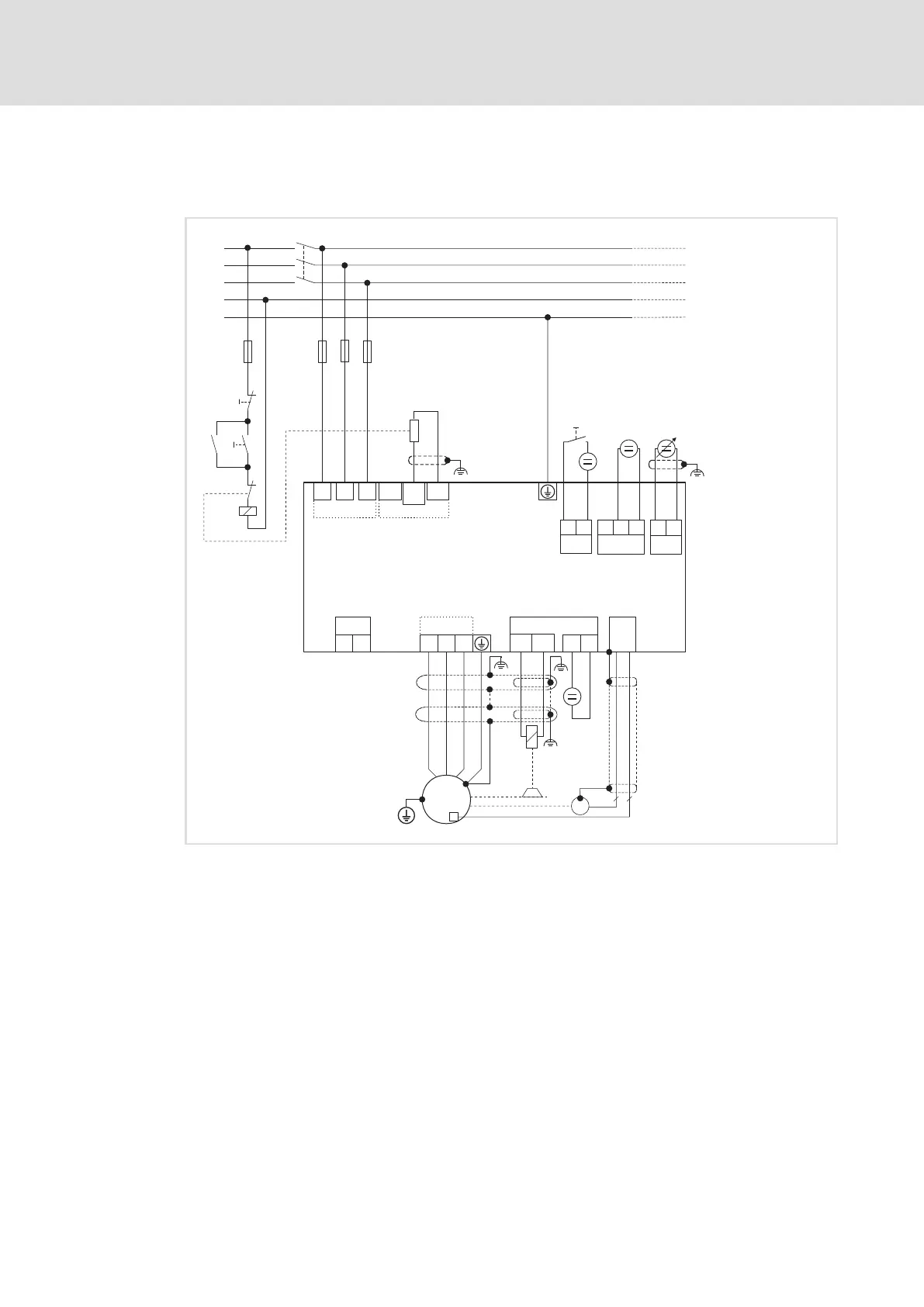
3.7.6 Devices in the range 145 ... 245 A (75 ... 130 kW)
Example circuit
L3
N
PE
L1
L2
F1...F3
F4
K1
K1
K1
L1 L2
L3
E94BSxExxxx
X100X100
-UG
Rb2
O
I
+UG
Rb1
R
B
U
VW
X105
BD1
BD2
X107
X7
T1
T2
X106
M
3~
R
Y
J
J
EYF...
7 2
+
-
+
-
X104
R
B
X2
24ESB GE
+
-
X3
+
-
A1-A1+
RFR
X5
GI
RFR
+
-
SSP94PSP89
Fig. 3−25 Basic circuit diagram of the drive system
E94BSxExxxx 9400 Single Drive servo axis module
F1 ... F4 Fusing
HF−shield termination through large−surface connection to PE
EYF... System cable for resolver feedback
RFR Controller enable
K1 Mains contactor
R Resolvers
RB Brake resistor
Y Motor holding brake
Speed setpoint selection via analog input 1 (−10 ... 0 ... +10 V)
Voltage source of the brake
24 V voltage source for the digital inputs according to IEC 61131−2
24 V voltage source for the control electronics

 Loading...


