DC−bus operation
Application examples
Example 2
7
362
EDS94SPP101 EN 10.2
7.7.2 Example 2 − single−axis controller with multi axes
Assumptions:
ƒ 400 V, 3 AC/PE
ƒ 4 axes in 3 power categories
ƒ no particular dynamic performance requirements
The following motors (Mx) are selected:
Motor type Rated power Efficiency Rated current
Index [kW] [A]
M1 MCS19P30 10.0 0.93 19
M2 MCS14H15 2.5 0.92 6.6
M3 ... M4 MCS09F38 1.2 0.90 2.5
For the above motor data, the following controllers (Gx) are selected:
Controller Rated power Typical motor
power
Power loss P
l
Rated current
Index [kW] [kW] [kW] [A]
G1 E94ASxE0244 16.3 11.0 0.50 23.5
G2 E94AMxE0074 4.8 3.0 0.19 7.0
G3 ... G4 E94AMxE0034 1.7 0.75 0.12 2.5
The power required by the drive system is determined with the below formula ( 7.5.5):
P
DCtotal
= (10 kW / 0.93 + 0.50 kW) + (2.5 kW / 0.92 + 0.19 kW) + 2 * (1.2 kW / 0.90 + 0.12 kW)
P
DCtotal
= 17.1 kW
The calculated power requirement is used to select the single−axis controller with mains
choke:
Controller (+ mains choke) Rated power (P
DC100%
)
Index [kW]
(G1) E94ASxE0244
+ E94AZMS0314
18.8
Note: Only the controller with mains choke reaches the required power.
Checking the power efficiency:
With 18.8 kW > 17.1 kW, P
DC100%
> P
DCtotal
.
Select cables and fuses in accordance with the Technical data.
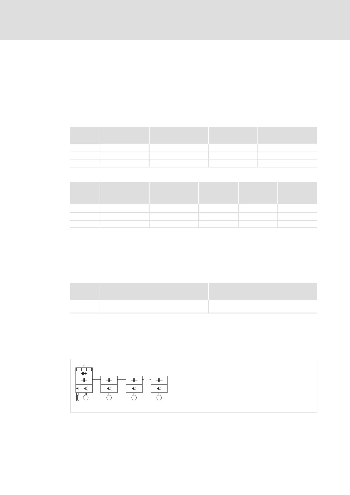
G1 Gx
...
MMM
L2L1
L3
3
AC
M
Fig. 7−5 Basic circuit diagram

 Loading...


