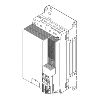
Regenerative power supply modules
Mechanical installation
Mounting steps
6
314
EDS94SPP101 EN 10.2
6.5.4 Mounting steps
Proceed as follows for the installation:
1. Prepare M5 threaded holes on the mounting plate according to the mounting grid.
2. Screw the installation backplane onto the mounting plate. Do not yet tighten the
screws.
– Use M5 screw and washer assemblies or M5 hexagon socket screws with washers.
– The screw joint in the installation backplane may not jut out more than 7 mm.
3. Repeat step 2 for other installation backplanes, which can be mounted directly
adjacent to one another.
4. Align all installation backplanes.
5. If busbars are used: connect the busbars.
6. Tightly screw all installation backplanes onto the mounting plate.
– Tightening torque: 3.4 Nm (30 lb−in).
Tip!
Before plugging the standard device into the installation backplane, read the
chapters "Disconnect internal PE connection" ( 320) and "Connecting
busbars" ( 323).

 Loading...


