Multi−axis controllers
Wiring
Devices in the range 2 ... 32 A (0.37 ... 15 kW)
4
206
EDS94SPP101 EN 10.2
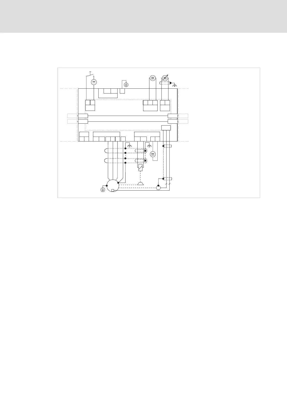
4.7.4 Devices in the range 2 ... 32 A (0.37 ... 15 kW)
Example circuit
E94AMxExxxx
X100
V
X105 X107
X3
X106
M
3~
R
Y
2
7
+
-
EYF...
X7
E94AZPxxxxx
T1
T2
U
W
BD1
BD2
+
-
A1-A1+
+UG
-UG
+
-
RFR
X5
GI
RFR
+
-
X109
X109
X109
X109
X110
X110
X110
X110
-UG
+UG
01
J
X2
24ESB GE
+
-
+
+
SSP94PSP31
Fig. 4−14 Basic circuit diagram of the drive system
E94AMxExxxx 9400 Multi Drive servo axis module
E94AZPxxxxx Installation backplane
DC power supply module or DC feeding point or axis module
Next axis module
HF shield termination through large−surface connection to functional earth
EYF... System cable for resolver feedback
RFR Controller enable
R Resolver
Y Motor holding brake (connected to optional motor brake control)
Speed setpoint selection via analog input 1 (−10 ... 0 ... +10 V)
Voltage source for the motor holding brake
24−V voltage source for the digital inputs according to IEC 61131−2
24−V voltage source for control electronics according to IEC 61131−2
Tip!
Complete the wiring of the installation backplane before plugging in the
standard device. The upper terminals of the installation backplane cannot be
connected with a plugged−in standard device.

 Loading...


