Single−axis controllers
Mechanical installation
Devices in the range 2 ... 24 A (0.37 ... 11 kW)
3
91
EDS94SPP101 EN 10.2
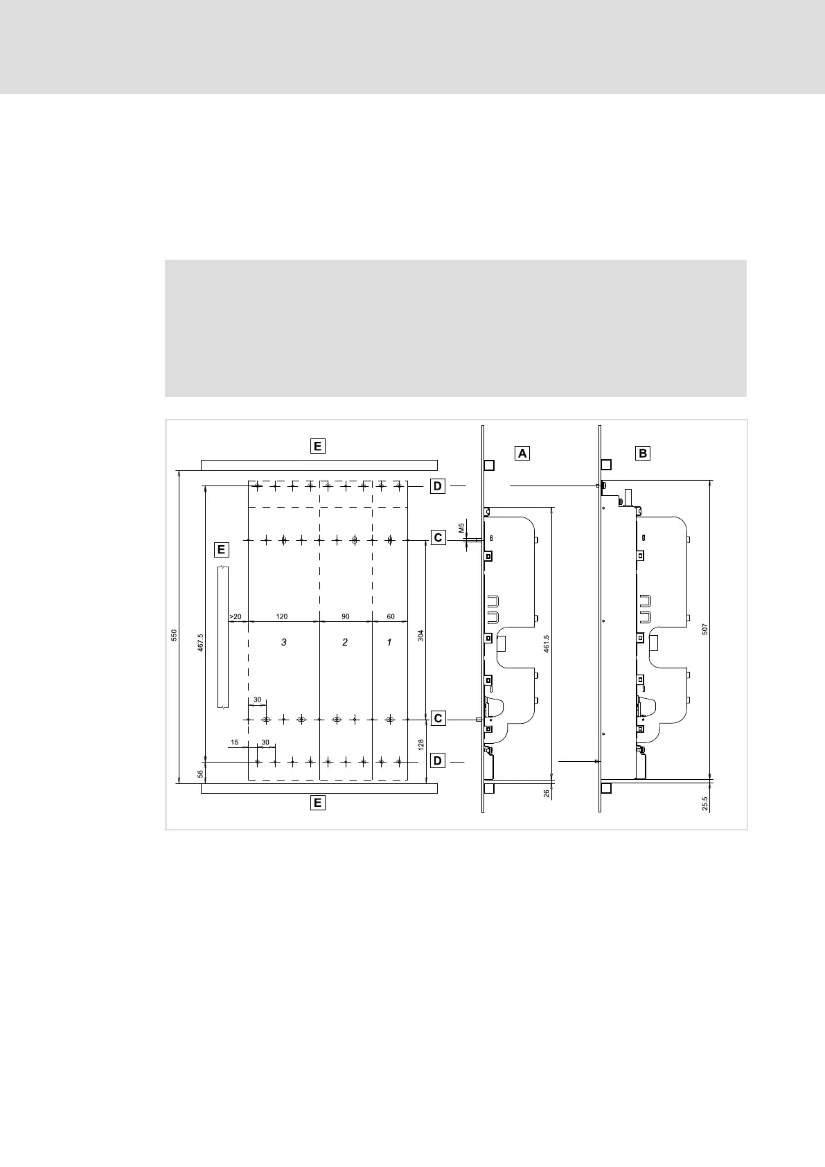
3.6.2 Devices in the range 2 ... 24 A (0.37 ... 11 kW)
Mounting grid
We recommend to provide the mounting plate with a grid pattern of M5 threaded holes
for attaching the devices. This preparation enables easy attachment of the devices, and the
device sizes 1, 2, ... n can thus be mounted directly adjacent to each other.
Note!
ƒ M5 screw and washer assemblies or hexagon socket screws with washers
are permitted.
ƒ Tightening torque: 3.4 Nm / 30 lb−in.
ƒ In the installation backplane, the screwed connection may not jut out more
than 7 mm.
9400SSP0010
Fig. 3−14 Mounting grid for installation backplane and filter of device sizes 1 ... 3
Installation backplane without footprint filter (mains or RFI filter)
Installation backplane with footprint filter
Grid hole pattern for installation backplane (M5 threaded holes)
Grid hole pattern for footprint filter (M5 threaded holes)
Cable duct
1 ... 3 Device size, mounting holes used
 Loading...


