Regenerative power supply modules
Wiring
Design of the cables
6
324
EDS94SPP101 EN 10.2
6.6.6 Design of the cables
ƒ The cables used must comply with the approvals required for the location (e.g. UL).
ƒ The cross−section of the PE conductor must be dimensioned according to the
relevant national regulations.
ƒ The effectiveness of a shielded cable is reached by:
– Providing a good shield connection through large−surface shield contact.
– Using only braided shields with low shield resistance made of tin−plated or
nickel−plated copper braid.
– Using braided shields with an overlap rate > 70 % and an overlap angle of 90 °.
– Keeping unshielded cable ends as short as possible.
Use system cables or shielded cables for these connections:
ƒ External brake resistor ( Mounting Instructions of the brake resistor)
ƒ Analog signals (inputs and outputs)
ƒ CAN system bus
ƒ Resolver
ƒ System connection for synchronisation
ƒ DC bus, cable length from 0.3 m
The following connections need not be shielded:
ƒ Mains
ƒ DC bus, cable length up to 0.3 m
ƒ 24 V supply
ƒ Digital signals (inputs and outputs)
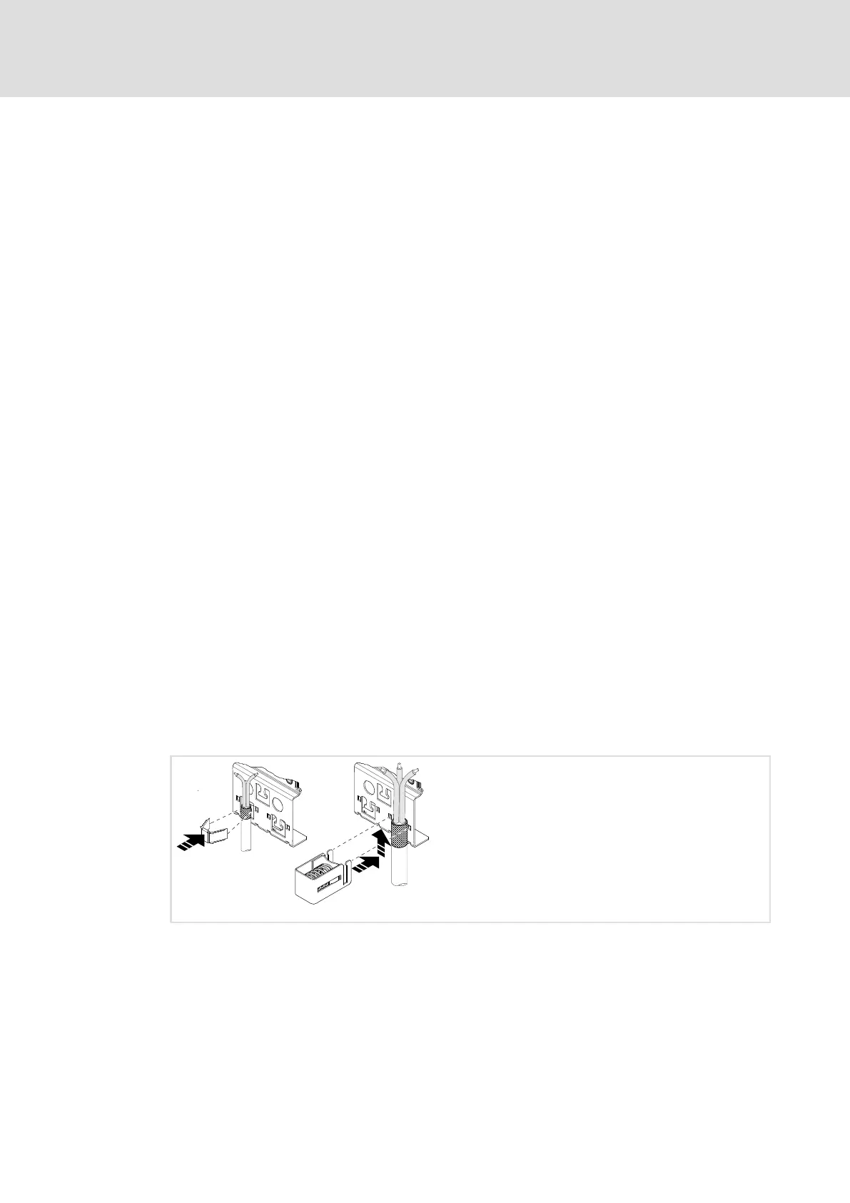
6.6.7 How to connect the shield
E94AZPS004

 Loading...


