4-79
TMS9000-2 OPERATOR MANUAL OPERATING PROCEDURES
Published 02-21-2019, Control # 611-05
• 4 parts of line on main hoist (no aux nose).
• Boom extension stowed.
Enter the Boom Configurator screen (should appear similar
to Figure 4-154).
Now highlight the first selection box at the top of the screen
(for radius), and select Enter. The value in the box can now
be changed. Increase the value until 70.0 ft is shown. Select
Enter. After a few moments, the boom configurations are
searched and sorted and then shown in the table similar to
Figure 4-155.
Next, highlight the second selection box (for hook load), and
select Enter. The value in the box can now be changed.
Increase the value until 9.0 klbs is shown. Again select Enter.
The boom configurations are now a shorter list (since now
matching for both radius and load).
Next, highlight the third selection box (for boom length), and
select Enter. The value in the box can now be changed.
Increase the value until 120.0 (ft) is shown. Again select
Enter. The boom configurations are now an even shorter list.
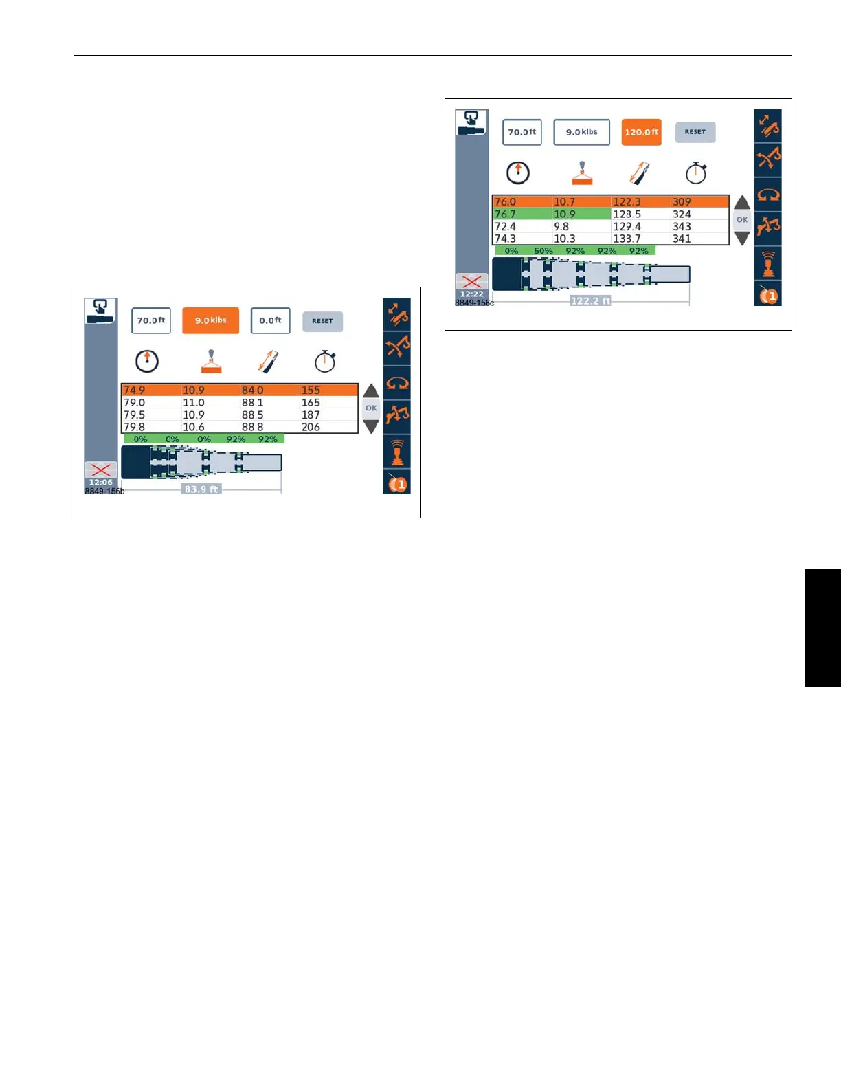
Figure 4-156 shows the expected typical boom
configurations for the three criteria that have been entered.
Note that the second row has the radius and load highlighted
in green. These green values indicate the maximum values
in the table; the 128.5 ft boom length pinning combination
has the highest possible radius and load. For the column
with the approximate time to extend the boom, the green
highlighted value is actually the minimum value (since a
shorter time is expected to be the most desirable). Also, note
that the orange color for highlighting/selecting a row can
“hide” the green color, but the italics is also used to try to
distinguish these items. Use the up and down arrow icons at
the right side of the screen to change the highlighted row and
then see all the green colored items.
Again referring to Figure 4-156, the second row could be
highlighted using the up and down arrows at the right side of
the screen. This would be pinning combination 0-50-100-
100-100. This may be considered the best selection since it
can also proceed to fully extended, if desired. The first row
might also be desirable since the approximate time to extend
is the fastest. Once a selection is made, the OK button can
be used (if the telescoping function has been activated) to
proceed to use the boom configuration in the Semi-auto
mode. Another option is to change the rigging information as
explained next.
The rigging information on the RCL display can be changed
as follows:
• Counterweight of 36,000 lbs.
• Use the check-mark to activate new rigging.
If the Boom Configurator screen is still shown, the table of
values should update.
Enter the following values with the selection boxes (the
values in the selection boxes may show values within 0.1 of
the desired value - just changing Load if retaining example
from above):
Radius = 70 (70.1 being acceptable)
Load = 18.0 (a higher load than above)
Length = 120.0
A new table of available boom configurations can appear
and a new selection can be made and sent to the Semi-auto
telescoping mode.
Finally, if it is desired to keep lifts within a criterion such as
75% of the maximum values for the load chart data, then the
search can be based on a modified hook load. The modified
hook load value would be the hook load divided by the
decimal value for the desired limitation such as the following:
P
modified
= P / 0.75

 Loading...


