99
4. BASIC OPERATION
4.3 Basic operation procedure (External operation)
3
4
5
4
5
6
7
8
9
10
4.3.3 Setting the frequency with analog signals (voltage input)
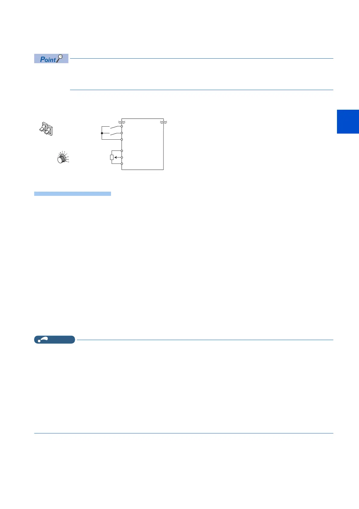
• Switch ON the STF (STR) signal to give a start command.
• Use the potentiometer (frequency setting potentiometer) to give a frequency command. (by connecting it
across terminals 2 and 5 (voltage input)).
[Connection diagram]
(The inverter supplies 5 V power to the frequency setting potentiometer (terminal 10).)
The following shows the procedure to operate at 60 Hz.
1. Screen at power-ON
The monitor display appears.
2. Start
Turn ON the start switch (STF or STR). [STF] or [STR] indicator is on.
3. Acceleration → constant speed
Turn the potentiometer (frequency setting potentiometer) clockwise slowly to full. The frequency value on the
indication increases in Pr.7 Acceleration time, and "60.00 Hz" appears. [FWD] indicator is on during the forward
rotation, and [REV] indicator is on during the reverse rotation.
4. Deceleration
Turn the potentiometer (frequency setting potentiometer) counterclockwise slowly to full. The frequency value on
the indication decreases in Pr.8 Deceleration time, and the motor stops rotating with "0.00 Hz" displayed. [FWD]
or [REV] indicator flickers.
5. Stop
Turn OFF the start switch (STF or STR). [STF] or [STR] indicator turns OFF.
NOTE
• When both the forward rotation switch (STF) and the reverse rotation switch (STR) are ON, the motor cannot be started.
If both are turned ON while the inverter is running, the inverter decelerates to a stop.
• Pr.178 STF terminal function selection must be set to "60" (or Pr.179 STR terminal function selection must be set to
"61"). (All are initial values.)
• When terminal 10 is used, the maximum output frequency may fluctuate in a range of ±6 Hz due to fluctuations in the output
voltage (5 ±0.5 VDC). Use Pr.125 or Pr.903 to adjust the output frequency at the maximum analog input as required. (Refer
to page 328.)
• When terminal 10E is used, the maximum output frequency may fluctuate (in a range of ±2 to 3 Hz) due to fluctuations in
the output voltage (10 ±0.4 VDC). Use Pr.125 or Pr.903 to adjust the output frequency at the maximum analog input as
required. (Refer to page 328.)
Inverter
Frequency setting
potentiometer
5
10
2
Forward rotation start
Reverse rotation start
STF
STR
SD
Switch
Potentiometer

 Loading...