310
5. PARAMETERS
5.8 (M) Monitor display and monitor output signal
5.8.10 Remote output function
The inverter output signals can be turned ON/OFF like the remote output terminals of a programmable controller.
Remote output setting (REM signal, Pr.496, Pr.497)
• The output terminal can be turned ON/OFF with the Pr.496 and Pr.497 settings. ON/OFF control can be performed for the
remote output terminal via the PU connector, RS-485 terminals and communication option.
• To assign the Remote output (REM) signal to the terminal to be used for remote output, set "96 (positive logic) or 196
(negative logic)" in any of Pr.190 to Pr.196 (Output terminal function selection).
• Refer to the left figure, and set "1" in the terminal bit (terminal with the REM signal assigned) of Pr.496 or Pr.497 to turn
ON the output terminal (OFF when using negative logic). Set "0" to turn OFF the output terminal (ON when using negative
logic).
• For example, when Pr.190 RUN terminal function selection = "96" (positive logic) and "1" (H01) is set in Pr.496, the
terminal RUN turns ON.
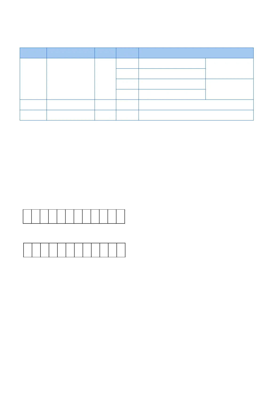
Pr.496
Pr.497
*1 Any value.
*2 Y0 to Y6 are available when the extension output option (FR-A8AY) is installed.
*3 RA1 to RA3 are available hen the relay output option (FR-A8AR) is installed.
Pr. Name Initial
value
Setting
range
Description
495
M500
Remote output selection 0 0 Remote output data is cleared when
the power supply is turned OFF
Remote output data is
cleared during an inverter
reset
1 Remote output data is retained when
the power supply is turned OFF
10 Remote output data is cleared when
the power supply is turned OFF
Remote output data is
retained during an inverter
reset
11 Remote output data is retained when
the power supply is turned OFF
496
M501
Remote output data 1 0 0 to 4095 Set values for the bits corresponding to each output terminal of the
inverter output terminal. (Refer to the diagram below.)
497
M502
Remote output data 2 0 0 to 4095 Set values for the bits corresponding to each output terminal of
options FR-A8AY and FR-A8AR. (Refer to the diagram below.)
b11 b0
ABC1
ABC2
∗1
∗1
∗1
∗1
∗1
FU
OL
IPF
SU
RUN
b11 b0
Y5 ∗2
Y6 ∗2
RA1 ∗3
RA2 ∗3
RA3 ∗3
∗1
∗1
Y4 ∗2
Y3 ∗2
Y2 ∗2
Y1 ∗2
Y0 ∗2

 Loading...