458
5. PARAMETERS
5.11 (A) Application parameters
5.11.14 Power failure time deceleration-to-stop function
This is a function to decelerate the motor to a stop when an instantaneous power failure or undervoltage occurs.
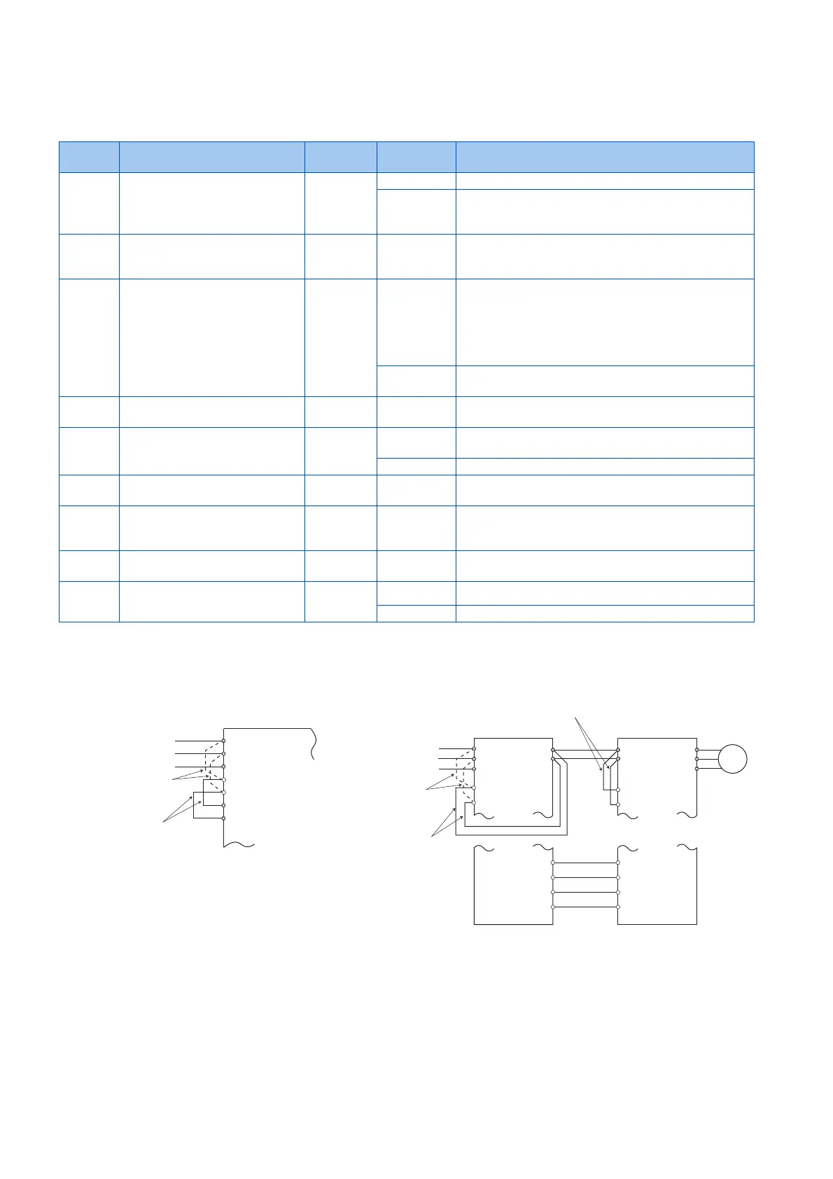
Connection and parameter setting
• For the standard model, remove the jumpers between terminals R/L1 and R1/L11 and terminals S/L2 and S1/L21, and
connect terminals R1/L11 and P/+ and terminals S1/L21 and N/-.
• If an undervoltage, power failure or input phase loss occurs when Pr.261 Power failure stop selection "0", the motor
decelerates to a stop.
Pr. Name Initial value Setting
range
Description
261
A730
Power failure stop selection 0 0 Power failure time deceleration-to-stop function disabled
1, 2, 11, 12,
21, 22
Power failure time deceleration-to-stop function enabled
Select action at an undervoltage or when an power failure
occurs.
262
A731
Subtracted frequency at
deceleration start
3 Hz 0 to 20 Hz Normally, the motor runs at the initial value as it is.
However, adjust to suit the size of the load specification
(moment of inertia, torque).
263
A732
Subtraction starting frequency 60 Hz 0 to 590 Hz When output frequency ≥ Pr.263:
The motor decelerates if the output frequency decreases
by the frequency set in Pr.262.
When output frequency < Pr.263:
The motor decelerates at frequencies of the output
frequency.
9999 The motor decelerates from the "output frequency -
Pr.262".
264
A733
Power-failure deceleration time 1 5 s 0 to 3600 s Set the slope applicable from the deceleration start to the
Pr.266 set frequency.
265
A734
Power-failure deceleration time 2 9999 0 to 3600 s Set the slope applicable for the frequency range starting at
Pr.266 and downward.
9999 Same as Pr.264.
266
A735
Power failure deceleration time
switchover frequency
60 Hz 0 to 590 Hz Set the frequency at which the slope during deceleration
switches from the Pr.264 setting to the Pr.265 setting.
294
A785
UV avoidance voltage gain 100% 0 to 200% Adjust the response at undervoltage avoidance operation.
Setting a large value improves the response to changes in
the bus voltage.
668
A786
Power failure stop frequency
gain
100% 0 to 200% Adjust the response level for the operation where the
deceleration time is automatically adjusted.
606
T722
Power failure stop external
signal input selection
1 0 Normally open input (NO contact input specification)
1 Normally closed input (NC contact input specification)
Power supply
Power supply
Remove the jumper
Inverter
S/L2
T/L3
S1/L21
P/+
N/-
R1/L11
R/L1
Remove the jumper
Converter unit
Inverter
Separated converter type
Standard models
R/L1
S/L2
T/L3
R1/L11
S1/L21
U
V
W
M
R1/L11
S1/L21
P/+
N/-
P/+
N/-
Connect terminals
R1/L11 and P/+
and terminals
S1/L21 and N/-.
Connect terminals
R1/L11 and P/+
and terminals
S1/L21 and N/-.
Keep the jumpers of terminal
R1/L11 and terminal S1/L21
connected.
RDA MRS(X10)
RSO RES
PWF X48
SE SD

 Loading...