63
2. INSTALLATION AND WIRING
2.6 Control circuit
3
2
3
4
5
6
7
8
9
10
2.6.6 When supplying 24 V external power to the control circuit
Connect the 24 V external power supply across terminals +24 and SD to turn the I/O terminal ON/OFF operation, keep the
operation panel ON, and carry out communication with other devices even at power-OFF state of inverter's main circuit power
supply. When the main circuit power supply is turned ON, the power supply source changes from the 24 V external power
supply to the main circuit power supply.
Specification of the applicable 24 V external power supply
Commercially available products (as of October 2020)
*1 For the latest information about OMRON power supply, contact OMRON corporation.
Starting and stopping the 24 V external power supply operation
• Supplying 24 V external power while the main circuit power is OFF starts the 24 V external power supply operation.
Likewise, turning OFF the main circuit power while supplying 24 V external power starts the 24 V external power supply
operation.
• Turning ON the main circuit power stops the 24 V external power supply operation and enables the normal operation.
NOTE
• During the 24 V external power supply operation, the inverter operation is disabled.
• In the initial setting, when the main power supply is turned ON during the 24 V external power supply operation, a reset is
performed in the inverter, then the power supply changes to the main circuit power supply. (The reset can be disabled using
Pr.30. (Refer to page 553.))
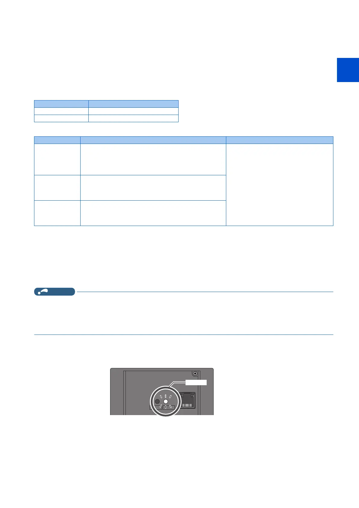
Confirming the 24 V external power supply input
• During the 24 V external power supply operation, the alarm lamp flickers.
• During the 24 V external power supply operation, the 24 V external power supply operation signal (EV) is output. To use
the EV signal, set "68 (positive logic) or 168 (negative logic)" in one of Pr.190 to Pr.196 (Output terminal function
selection) to assign function to an output terminal.
Item Rated specification
Input voltage 23 to 25.5 VDC
Input current 1.4 A or less
Model Product overview Manufacturer
S8FS-G05024C
*1
Specifications: Capacity 50 W, output voltage 24 VDC, output
current 2.2 A
Installation method: Direct installation, screw type terminal block
with cover
Input: Single-phase 100 to 240 VAC
OMRON Corporation
S8VK-S06024
*1
Specifications: Capacity 60 W, output voltage 24 VDC, output
current 2.5 A
Installation method: DIN rail, push-in (spring) type terminal block
Input: Single-phase 100 to 240 VAC
S8VK-WA24024
*1
Specifications: Capacity 240 W, output voltage 24 VDC, output
current 10 A
Installation method: DIN rail, push-in (spring) type terminal block
Input: Three-phase 200 to 240 VAC
POWER ALARM
Flickering

 Loading...