68
2. INSTALLATION AND WIRING
2.7 Communication connectors and terminals
USB device communication
The inverter can be connected to a personal computer with a USB (Ver. 1.1) cable.
Parameter setting and monitoring can be performed by using FR Configurator2.
• For details on FR Configurator2, refer to the Instruction Manual of FR Configurator2.
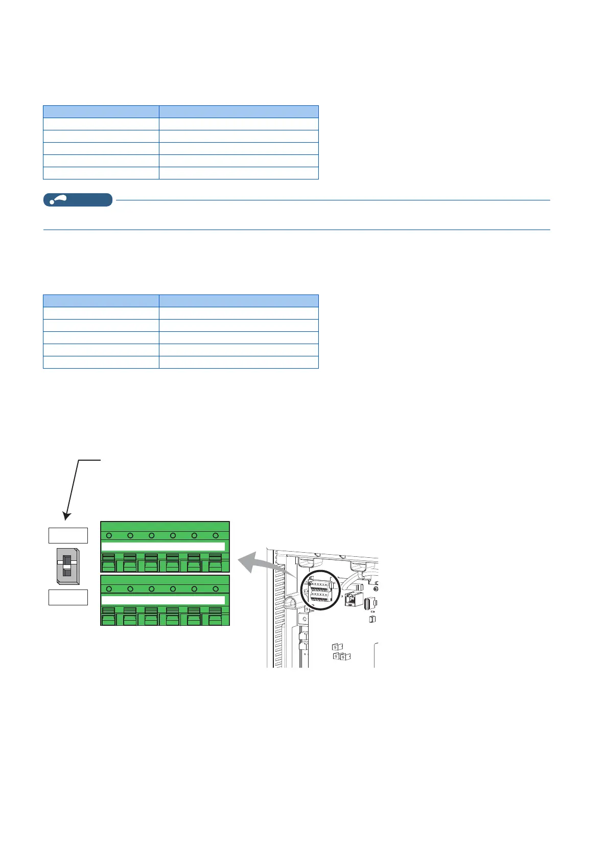
2.7.3 RS-485 terminal block
Communication operation
The RS-485 terminals enable communication operation from a personal computer, etc. When the PU connector is connected
with a personal, FA or other computer by a communication cable, a user program can run to monitor the inverter or read and
write parameters.
Communication can be performed with the Mitsubishi inverter protocol (computer link operation) and MODBUS RTU protocol.
For the details, refer to page 475.
Item Specification
Interface Conforms to USB 1.1
Transmission speed 12 Mbps
Wiring length Maximum 5 m
Connector USB mini B connector (receptacle)
Power supply Self-powered
Item Specification
Conforming standard EIA-485 (RS-485)
Transmission format Multidrop link
Communication speed Maximum 115200 bps
Overall length 500 m
Connection cable Twisted pair cable (4 pairs)
Terminating resistor switch
Initially-set to "OPEN".
Set only the terminating resistor switch of
the remotest inverter to the "100Ω" position.
OPEN
100Ω
+-+
TXD RXD
-
VCC GND
+-+
TXD RXD
-
VCC GND
RDA1
(RXD1+)
RDB1
(RXD1-)
RDA2
(RXD2+)
RDB2
(RXD2-)
SDA1
(TXD1+)
SDB1
(TXD1-)
SDA2
(TXD2+)
SDB2
(TXD2-)
P5S
(VCC)
SG
(GND)
P5S
(VCC)
SG
(GND)

 Loading...