54
2. INSTALLATION AND WIRING
2.6 Control circuit
2.6.2 Control logic (sink/source) change
Change the control logic of input signals as necessary.
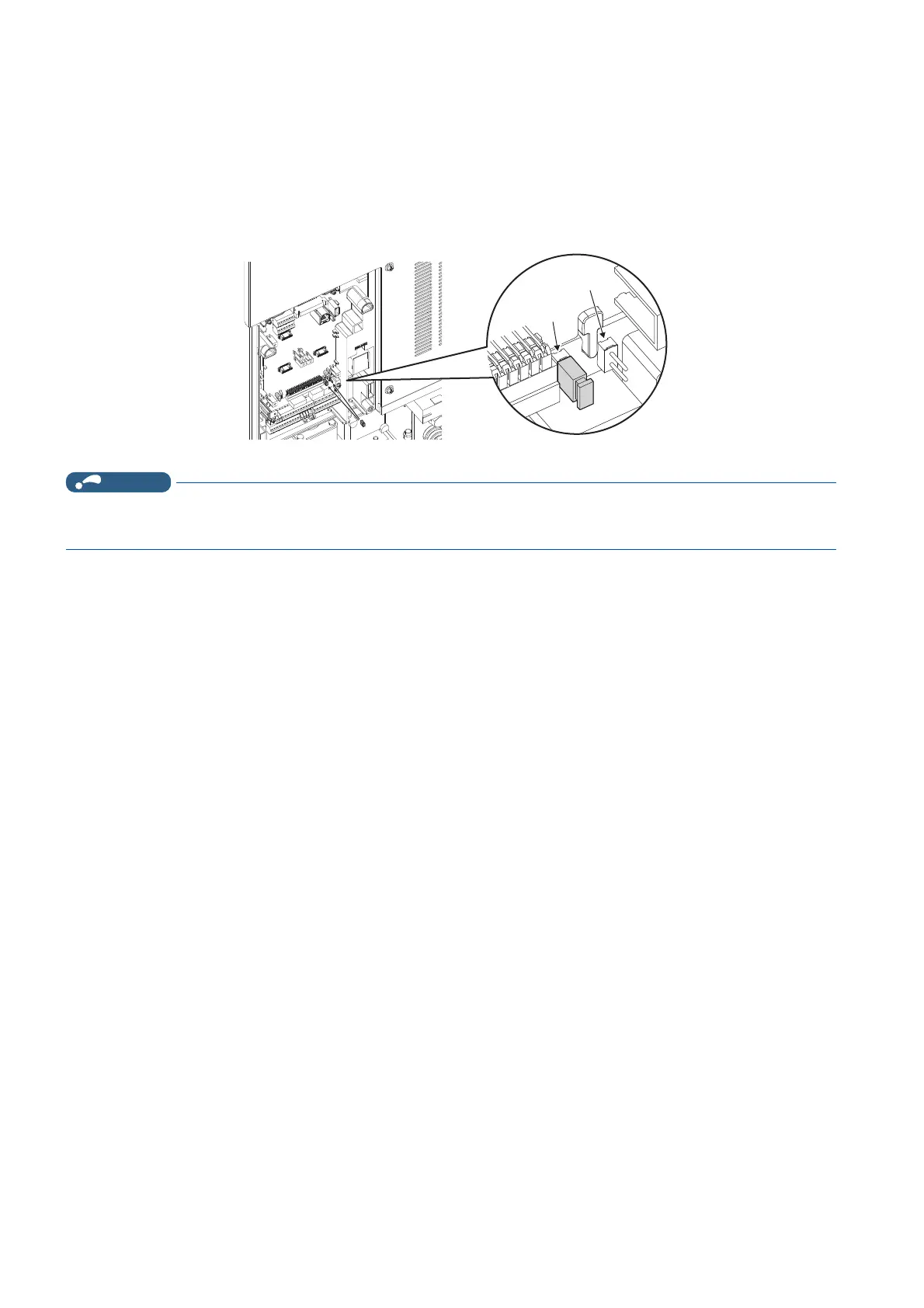
To change the control logic, change the jumper connector position on the control circuit board.
Connect the jumper connector to the connector pin of the desired control logic.
The control logic of input signals is initially set to the sink logic (SINK).
(The output signals may be used in either the sink or source logic independently of the jumper connector position.)
• Make sure that the jumper connector is installed correctly.
• Never change the control logic while power is ON.
Jumper connectorJumper connectorJumper connector
For sink logic
SOURCE
SINK

 Loading...