187
5. PARAMETERS
5.4 (E) Environment setting parameters
3
4
5
5
5
6
7
8
9
10
• The Y95 signal turns ON when any of MT1, MT2 or MT3 is activated. It does not turn OFF unless all of MT1, MT2 and MT3
are cleared.
• If all of MT1, MT2 and MT3 are activated, they are displayed in the priority of "MT1 > MT2 > MT3".
• The cumulative energization time is counted every hour. Energization time of less than 1 h is not counted.
• Changing the terminal assignment using Pr.190 to Pr.196 (Output terminal function selection) may affect the other
functions. Set parameters after confirming the function of each terminal.
Pr.190 to Pr.196 (Output terminal function selection) page 297
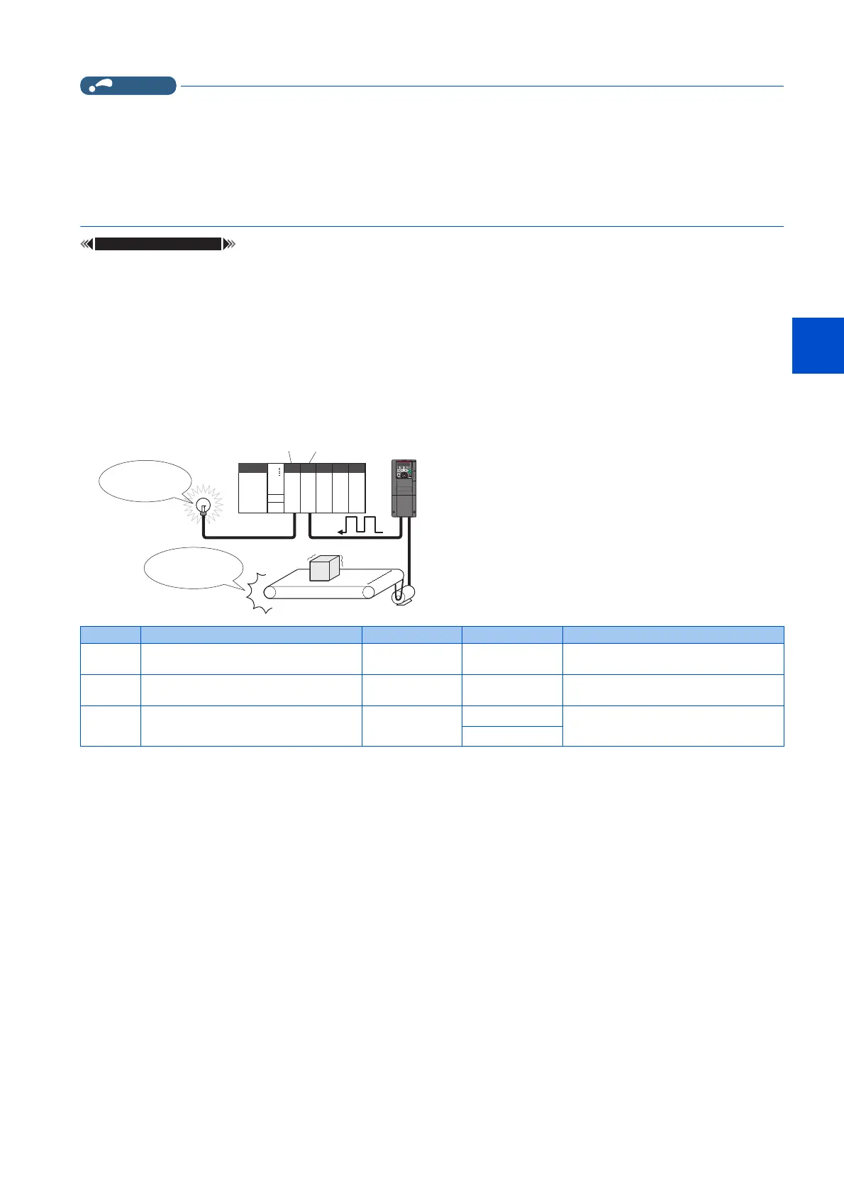
5.4.18 Current average value monitor signal
The output current average value during constant-speed operation and the maintenance timer value are output to the Current
average monitor (Y93) signal as a pulse. The output pulse width can be used in a device such as the I/O unit of a programmable
controller as a guideline for the maintenance time for mechanical wear, belt stretching, or deterioration of devices with age.
The pulse is repeatedly output during constant-speed operation in cycles of 20 s to the Current average monitor (Y93) signal.
*1 Initial value for the FR-F860-00680 or lower.
*2 Initial value for the FR-F860-01080 and higher.
Pr. Name Initial value Setting range Description
555
E720
Current average time 1 s 0.1 to 1 s Set the time for calculating the average
current during start pulse output (1 s).
556
E721
Data output mask time 0 s 0 to 20 s Set the time for not obtaining (masking)
transitional state data.
557
E722
Current average value monitor signal
output reference current
Inverter rated
current
0 to 500 A
*1
Set the reference (100%) for outputting
the output current average value signal.
0 to 3600 A
*2
Parametersreferredto
Programmable controller
Output
unit
Input
unit
maintenance
time
parts have
reached their life
Inverter

 Loading...