83
3. PRECAUTIONS FOR USE OF THE INVERTER
3.7 Failsafe system which uses the inverter
3
4
3
4
5
6
7
8
9
10
3.7 Failsafe system which uses the inverter
When a fault is detected by the protective function, the protective function activates and outputs a fault signal. However, a fault
signal may not be output at an inverter's fault occurrence when the detection circuit or output circuit fails, etc. Although
Mitsubishi Electric assures the best quality products, provide an interlock which uses inverter status output signals to prevent
accidents such as damage to the machine when the inverter fails for some reason. Also at the same time consider the system
configuration where a failsafe from outside the inverter, without using the inverter, is enabled even if the inverter fails.
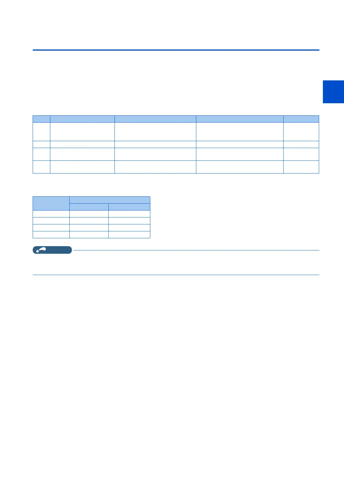
Interlock method which uses the inverter status output signals
By combining the inverter output signals to provide an interlock as shown below, an inverter failure can be detected.
• When using various signals, assign the functions to Pr.190 to Pr.196 (Output terminal function selection) referring to
the following table.
NOTE
• Changing the terminal assignment using Pr.190 to Pr.196 (Output terminal function selection) may affect the other
functions. Set parameters after confirming the function of each terminal.
No. Interlock method Check method Used signals Refer to page
a Inverter protective function
operation
Operation check of an alarm contact.
Circuit error detection by negative
logic.
Fault (ALM) signal 304
b Inverter operating status Operation ready signal check. Inverter operation ready (RY) signal 303
c Inverter running status Logic check of the start signal and
running signal.
Start signal (STF signal, STR signal)
Inverter running (RUN) signal
303, 550
d Inverter running status Logic check of the start signal and
output current.
Start signal (STF signal, STR signal)
Output current detection (Y12) signal
307, 550
Output signal Pr.190 to Pr.196 setting
Positive logic Negative logic
ALM 99 199
RY 11 111
RUN 0 100
Y12 12 112

 Loading...