72
3. PRECAUTIONS FOR USE OF THE INVERTER
3.1 Electro-magnetic interference (EMI) and leakage currents
3 PRECAUTIONS FOR USE OF THE INVERTER
This chapter explains the precautions for use of this product.
Always read the instructions before using the equipment.
For the PRECAUTIONS FOR USE OF THE INVERTER of the separated converter type, refer to the FR-F862 (Separated
Converter Type) Instruction Manual (Hardware).
3.1 Electro-magnetic interference (EMI) and leakage
currents
3.1.1 Leakage currents and countermeasures
Capacitance exist between the inverter I/O cables, other cables and earth and in the motor, through which a leakage current
flows. Since its value depends on the static capacitance, carrier frequency, etc., low acoustic noise operation at the increased
carrier frequency of the inverter will increase the leakage current. Therefore, take the following countermeasures. Select the
earth leakage current breaker according to its rated sensitivity current, independently of the carrier frequency setting.
To-earth (ground) leakage currents
Leakage currents may flow not only into the inverter's own line but also into the other lines through the earthing (grounding)
cable, etc. These leakage currents may operate earth leakage circuit breakers and earth leakage relays unnecessarily.
Countermeasures
• If the carrier frequency setting is high, decrease the Pr.72 PWM frequency selection setting. Note that motor noise
increases. Selecting Pr.240 Soft-PWM operation selection makes the sound inoffensive.
• By using earth leakage circuit breakers designed for harmonic and surge suppression in the inverter's own line and other
line, operation can be performed with the carrier frequency kept high (with low noise).
• Long wiring will increase the leakage current.
• High motor capacity will increase the leakage current.
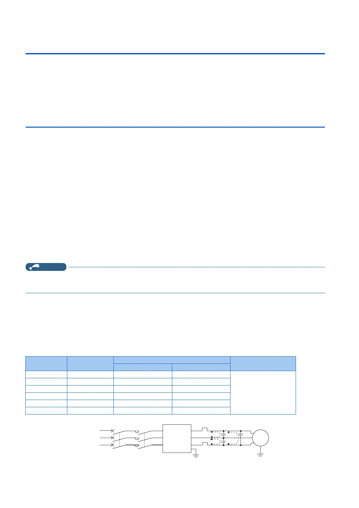
Line-to-line leakage currents
Harmonics of leakage currents flowing in static capacitance between the inverter output cables may operate the external
thermal relay unnecessarily. When the wiring length is long (50 m or more) for the 600 V class small-capacity models (FR-
F860-00170 or lower), the external thermal relay is likely to operate unnecessarily because the ratio of the leakage current to
the rated motor current increases.
Line-to-line leakage current example (600 V class)
Motor capacity
(kW)
Rated motor
current (A)
Leakage current (mA) Condition
Wiring length 50 m Wiring length 100 m
0.75 1.1 1020 1590 • Motor: 4P
• Carrier frequency: 14.5
kHz
• Cable: 2 mm
2
, 4 cores
• Cabtyre cable
1.5 2.0 1110 1680
2.2 3.2 1200 1770
3.7 5.2 1320 1890
5.5 7.8 1470 2040
7.5 9.9 1605 2175
Power
supply
Thermal relay
Line-to-line static
capacitance
MCCB MC
Line-to-line leakage currents path
Motor
Inverter/
converter
M

 Loading...