76
3. PRECAUTIONS FOR USE OF THE INVERTER
3.2 Power supply harmonics
3.2 Power supply harmonics
3.2.1 Power supply harmonics
The inverter may generate power supply harmonics from its converter circuit to affect the power generator, power factor
correction capacitor etc. Power supply harmonics are different from noise and leakage currents in source, frequency band and
transmission path. Take the following countermeasure suppression techniques.
• The differences between harmonics and noises
• Countermeasures
The harmonic current generated from the inverter to the input side differs according to various conditions such as the wiring
impedance, whether a reactor is used or not, and output frequency and output current on the load side.
For the output frequency and output current, we understand that this should be calculated in the conditions under the rated
load at the maximum operating frequency.
• The power factor improving capacitor and surge suppressor on the inverter output side may be overheated or damaged
by the harmonic components of the inverter output. Also, since an excessive current flows in the inverter to activate
overcurrent protection, do not provide a capacitor and surge suppressor on the inverter output side when the motor is
driven by the inverter. For power factor improvement, install a reactor on the inverter input side or in the DC circuit.
3.3 Installation of a reactor
When the inverter is connected near a large-capacity power transformer (1000 kVA or more) or when a power factor correction
capacitor is to be switched over, an excessive peak current may flow in the power input circuit, damaging the converter circuit.
To prevent this, always install an AC reactor, which is available as an option.
Item Harmonics Noise
Frequency Normally 40th to 50th degrees or less (3
kHz or less).
High frequency (several 10 kHz to 1 GHz order).
Location To-electric channel, power impedance. To-space, distance, wiring path,
Quantitative understanding Theoretical calculation possible. Random occurrence, quantitative grasping difficult.
Generated amount Nearly proportional to the load capacity. Changes with the current variation ratio. (Gets larger as
switching speed increases.)
Affected equipment immunity Specified by standards per equipment. Different depending on maker's equipment specifications.
Countermeasure Provide a reactor. Increase distance.
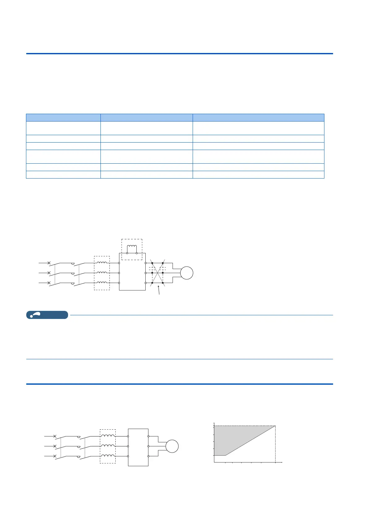
AC reactor
DC reactor
Do not install power
factor improving capacitor.
MCCB MC
Inverter
Power supply
R
S
TZ
Y
X
U
V
W
P1
R/L1
S/L2
T/L3
P/+
M
MCCB MC
Inverter
AC reactor
Power
supply
R
S
T
Z
Y
X
U
V
W
R/L1
S/L2
T/L3
M
5000
5300
4000
3000
2000
1000
110165 247 330 420 550 kV
Capacities requiring
installation of
AC reactor
Inverter capacity
Power supply system
capacity
(kVA)

 Loading...