69
2. INSTALLATION AND WIRING
2.8 Connection of stand-alone option units
3
2
3
4
5
6
7
8
9
10
2.8 Connection of stand-alone option units
The inverter accepts a variety of stand-alone option units as required.
Incorrect connection will cause inverter damage or accident. Connect and operate the option unit carefully in accordance with
the corresponding option unit manual.
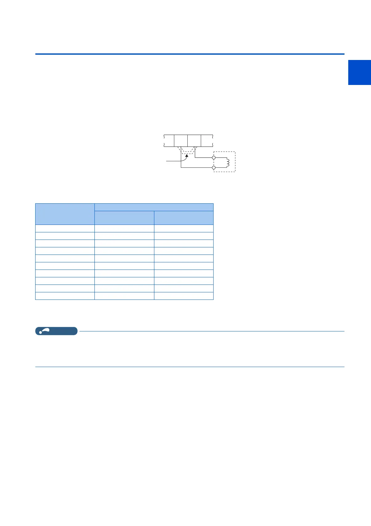
2.8.1 Connection of the DC reactor
• When using the DC reactor, connect it across terminals P/+ and P1. In this case, the jumper connected across terminals
P/+ and P1 must be removed. Otherwise, the reactor will not be effective. (The jumper is not installed for the FR-F860-
01080 or higher.)
• Select a DC reactor according to the applied motor capacity. (Refer to page 612.)
• For the FR-F860-01080 or higher, or whenever a 75 kW or higher motor is used, always connect a DC reactor.
• Select a DC reactor according to the following table.
*1 The power supply frequency of 60 Hz is assumed.
*2 Class H or higher insulation is recommended.
Select a DC reactor for which its L value does not fall to 50% or below when the inverter overload current rating is 150% (SLD rating).
NOTE
• The wiring distance must be within 5 m.
• As a reference, the cable gauge for the connection must be equal to or larger than that of the power supply cables (R/L1,
S/L2, T/L3) and the earthing (grounding) cable. (Refer to page 44.)
Motor capacity (kW) Reactor specifications
*1*2
Reactor L value (mH) DC reactor
rated current (A)
75 0.616 124
90 0.517 149
110 0.426 182
132 0.351 219
160 0.294 265
185 0.254 307
220 0.214 365
250 0.188 414
280 0.169 464
315 0.150 522
P1
DC reactor
Remove
the jumper
P/+

 Loading...