5-37
5
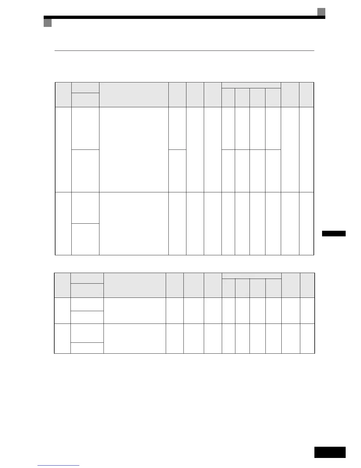
Protection Function Parameters: L
Motor Overload: L1
Power Loss Settings: L2
Para-
meter
Num-
ber
Name
Description
Setting
Range
Factory
Setting
Change
during
Opera-
tion
Control Methods
MEMO-
BUS
Register
Page
V/f
Open
Loop
Vector
Closed
Loop
Vector
Closed
Loop
Vector
(PM)
Display
L1-01
Motor pro-
tection selec-
tion
Sets whether the motor thermal over-
load protection function is enabled or
disabled.
0:Disabled
1:General-purpose motor protection
(fan cooled motor)
2:Inverter motor protection (exter-
nally cooled motor)
3:Vector motor protection
When the Inverter power supply is
turned off, the thermal value is
reset, so even if this parameter is
set to 1, protection may not be
effective.
5:Permanent magnet constant torque
motor protection
0 to 3
i
No
Q
1
Q
1
Q
1
-
480H 6-44
MOL Fault
Select
0 or 5 - - -
A
5
L1-02
Motor pro-
tection time
constant
Sets the electric thermal detection
time in seconds units.
Usually changing this setting is not
necessary.
The factory setting is 150% overload
for one minute.
When the motor's overload capabil-
ity is known, also set the overload
resistance protection time for when
the motor is hot started.
0.1 to
5.0
1.0 min No A A A -A 481H 6-44
MOL Time
Const
Para-
meter
Num-
ber
Name
Description
Setting
Range
Factory
Setting
Change
during
Opera-
tion
Control Methods
MEMO-
BUS
Register
Page
V/f
Open
Loop
Vector
Closed
Loop
Vector
Closed
Loop
Vector
(PM)
Display
L2-05
Undervoltage
detection level
Sets the DC bus undervoltage
(UV) detection level (DC bus
voltage).
150 to
210
*1
*1. These are values for a 200 V class Inverter. The value for a 400 V class Inverter is the double.
190 VDC
*1
No A A A A 489H -
PUV Det Level
L2-11
Rescue Opera-
tion DC bus
Voltage
Sets the DC bus voltage during
rescue operation.
0 to
400
*1
0 VDC No A A A A 4CBH 6-77
Volt@batterydr
 Loading...


