6-25
6
Adjusting Analog Input Signals
Adjusting Analog Frequency References
Using the H3- parameters, the analog input values of terminal A1 or the Channels 1 to 3 of the optional
analog input card AI-14B can be adjusted.
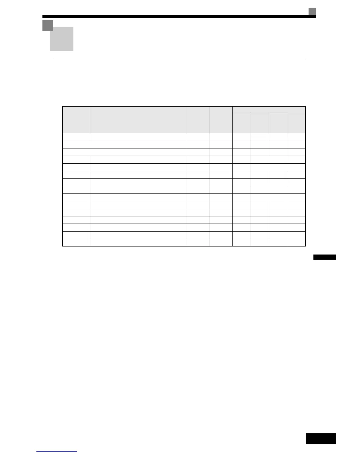
Related Parameters
Adjusting Analog Input Signals
The frequency reference can be input from the control circuit terminals using analog voltage. The voltage
level at terminal A1 is 0 to +10V. The analog input channels of the AI-14B option card can be used with 0 to
+10V or -10 to +10V.
The input signal levels can be selected using,
• H3-01 for AI-14B CH1
• H3-04 for AI-14B CH3
• H3-08 for AI-14B CH2
The signals can be adjusted using the parameters:
• H3-02 (Gain) and H3-03 (Bias) for Channel 1 of the AI-14B option card
• H3-06 (Gain) and H3-07 (Bias) for Channel 3 of the AI-14B option card
• H3-10 (Gain) and H3-11 (Bias) for Channel 2 of the AI-14B option card
• H3-16 (Gain) and H3-17 (Bias) for analog input A1
The gain sets the level of the selected input value if 10V is input, the bias sets the level of the selected input
value if 0V is input.
Parameter
No.
Name
Factory
Setting
Change
during
Operation
Control Methods
V/f
Open
Loop
Vector
Closed
Loop
Vector
Closed
Loop
Vector
(PM)
H3-01 Frequency reference AI-14B CH1signal level selection 0 No A A A A
H3-02 Frequency reference AI-14B CH1 input gain 100.0% Yes A A A A
H3-03 Frequency reference AI-14B CH1 input bias 0.0% Yes A A A A
H3-04 AI-14B CH3 signal level selection 0 No A A A A
H3-05 AI-14B CH3 function selection 2 No A A A A
H3-06 AI-14B CH3 input gain 100.0% Yes A A A A
H3-07 AI-14B CH3 input bias 0.0% Yes A A A A
H3-08 AI-14B CH2 signal level selection 3 No A A A A
H3-09 AI-14B CH2 function selection 0 No A A A A
H3-10 AI-14B CH2 input gain 100.0% Yes A A A A
H3-11 AI-14B CH2 input bias 0.0% Yes A A A A
H3-12 Analog input filter time constant for the AI-14B 0.03 s No A A A A
H3-15 Terminal A1 function selection 0 No - - A A
H3-16 Terminal A1 input gain 100.0% Yes A A A A
H3-17 Terminal A1 input bias 0.0% Yes A A A A
 Loading...


