5-3
5
Digital Operation Display Functions and Levels
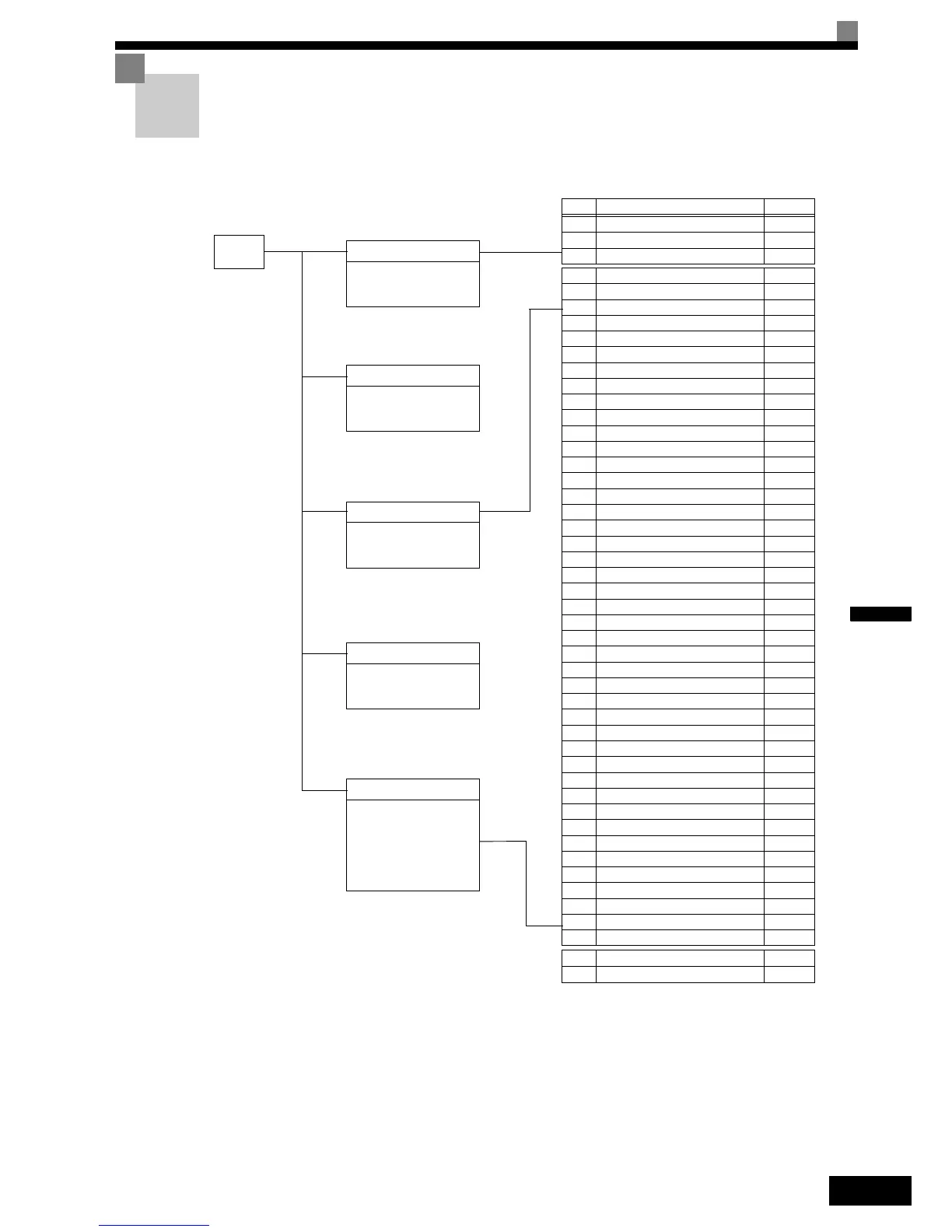
The following figure shows the Digital Operator display hierarchy for the Inverter.
MENU
Drive Mode
Inverter can be operated and
its status can be displayed.
Quick Programming Mode
Minimum parameters required
for operation can be monitored
or set.
Advanced Programming Mode
All parameters can be moni-
tored or set.
Verify Mode
Parameters changed from the
default settings can be
monitored or set.
Autotuning Mode
Automatically sets motor
parameters for vector control
or measures the line-to-line
resistance for V/f control.
No. Function Page
U1 Status Monitor Parameters
5-55
U2 Fault Trace
5-59
U3 Fault History
5-60
A1 Initialize Mode
5-8
A2 User-specified Setting Mode
5-9
b1 Operation Mode Selections
5-10
b2 DC Injection Braking
5-10
b4 Timer Function
5-11
b6 Dwell Functions
5-11
C1 Acceleration/Deceleration
5-12
C2 S-curve Acceleration/Deceleration
5-13
C3 Motor Slip Compensation
5-14
C4 Torque Compensation
5-15
C5 Speed Control (ASR)
5-16
C6 Carrier Frequency
5-16
d1 Speed References
5-18
d6 Field Forcing
5-20
E1 V/f Pattern 1
5-21
E2 Motor Setup 1
5-22
E3 V/f Pattern 2
5-23
E4 Motor Setup 2
5-24
E5 PM Motor Setup
5-25
F1 PG Option Setup
5-26
F4 Analog Monitor Card
5-29
F5 Digital Output Card
5-30
F6 Serial Communications Settings
5-31
H1 Multi-function Digital Inputs
5-32
H2 Multi-function Digital Outputs
5-33
H3 Multi-function Analog Inputs
5-35
L1 Motor Overload
5-37
L2 Power Loss Ridethrough
5-37
L3 Stall Prevention
5-38
L4 Reference Detection
5-38
L5 Fault Restart
5-39
L6 Torque Detection
5-40
L7 Torque Limits
5-41
L8 Hardware Protection
5-41
n2 Automatic Frequency Regulator
5-43
n5 Feed Forward Control
5-43
n8 PM Motor Adjustment
5-44
o1 Monitor Selection
5-45
o2 Digital Operator
5-46
o3 Copy Function
5-47
S1 Brake Sequence
5-47
S2 Slip Compensation
5-50
S3 Special Sequence Functions
5-51
T1 Motor Autotuning 1
5-53
T2 Motor Autotuning 2
5-54
 Loading...


