6-37
6
A/D Conversion Delay Time Tuning
The A/D conversion delay timer sets a delay for the current signal A/D conversion.
Related Parameters
Adjustments
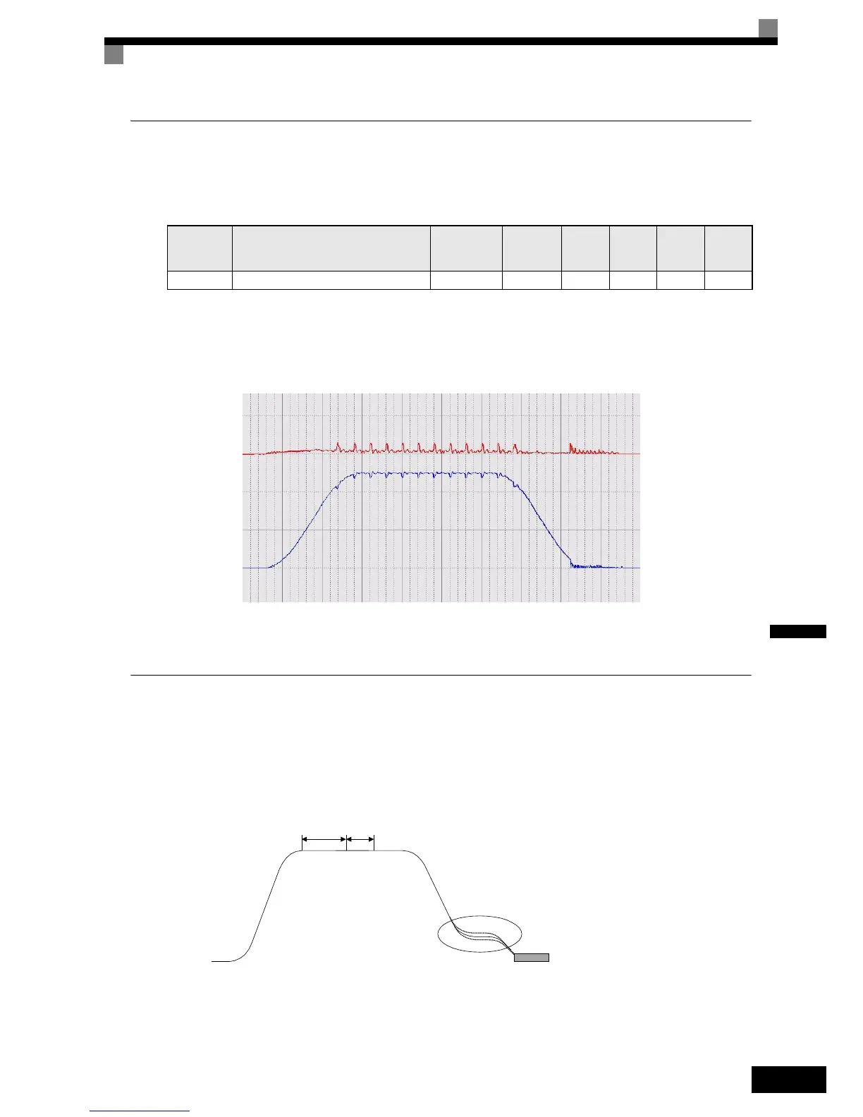
Normally an adjustment is no need to change this value. However, if cyclic oscillations like shown in Fig 6.13
occur during constant speed run, the A/D conversion delay can be increased in order to eliminate the vibra-
tions.
Fig 6.13 Oscillations caused by bad A/D conversion adjustment
Improving the Leveling Accuracy by Leveling Speed Slip Compensation
This function can be used in V/f and Open Loop Vector control to improve the leveling accuracy by compen-
sating the motor slip influence at leveling speed.
The inverter measures the current level or torque reference S2-05 sec. after the speed-agree condition (acceler-
ation finished) for the time set in S2-06 and calculates the average value to estimate the load. This value is
used for the calculation of slip which is added to the speed reference at leveling speed (see Fig 6.14).
Fig 6.14 Slip Compensation Working Principle
Parameter
No.
Name
Factory
setting
Change
during
operation
V/f
Open
Loop
Vector
Closed
Loop
Vector
Closed
Loop
Vector
(PM)
n9-60 Current signal A/D conversion delay time 0.0 µsec. No - - - A
Motor Speed
Torque Signal
S2-05
S2-06
Speed reference is increased
or decreased depending on
measured load
 Loading...


