6-3
6
Control / Brake Sequence
Up and Down Commands
Travel start in Up or Down direction
UP and Down commands are the travel direction information.
To start in the elevator in Up or Down direction the following conditions have to be fulfilled:
• At least one speed reference must be selected if digital inputs are used for speed reference selection.
• The hardware base block signal must be set (not base block condition).
• When a digital input is set as contactor confirmation input, the contactor confirmation signal must be
present before the travel starts.
• To start in the Up direction the Up signal must be set. To start in the Down direction the Down signal must
be set.
Travel stop
The inverter can be stopped as follows:
• The direction command (UP or Down) signal is removed.
• The speed reference selection signal is removed if digital inputs are used for speed reference selection.
• If d1-18 is set to 3 and all speed inputs are removed
Up / Down Command Source Selection
The input source for the Up and Down signal can be selected in parameter b1-02.
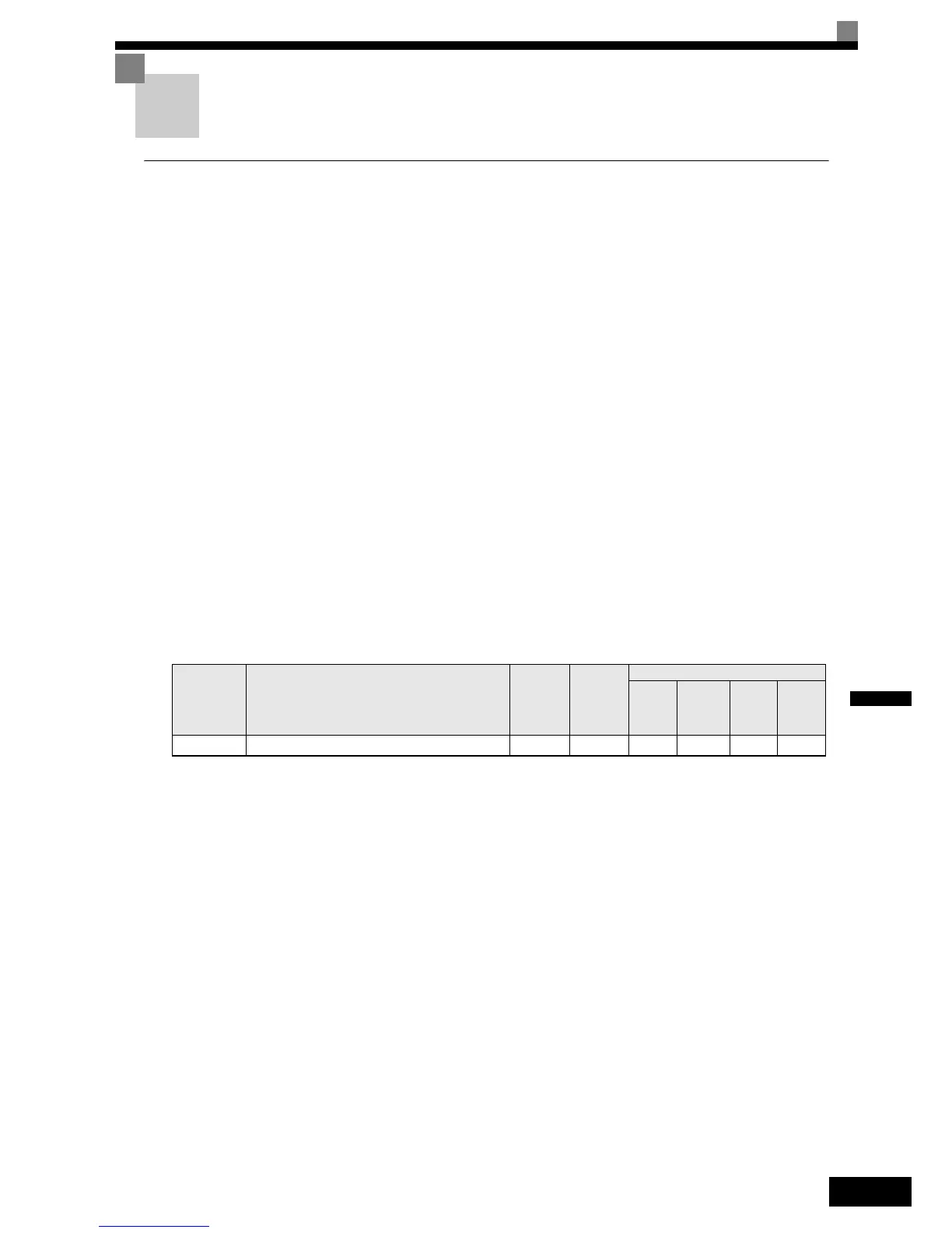
Related Parameters
Up/Down Commands Using the Digital Operator (b1-02=0)
When b1-02 is set to 0 the Up/Down command must be input using the Digital Operator keys (RUN, STOP,
and FWD/REV). For details on the Digital Operator refer to page 3-1, LED Monitor / Digital Operator and
Modes. This operation can be used for test purposes only.
Up/Down Commands Using Control Circuit Terminals (b1-02=1, factory setting)
When b1-02 is set to 1 the Up/Down command is input at the control circuit terminals S1 and S2. This is the
factory setting and the most common configuration.
Up/Down Commands Using an Input Option Card (b1-02=3)
When b1-02 is set to 2 the Up/Down command can be set using an input option card, for example a field bus
communications card.
Parameter
No.
Name
Factory
Setting
Change
during
Operation
Control Methods
V/f
Open
Loop
Vector
Closed
Loop
Vector
Closed
Loop
Vector
(PM)
b1-02 RUN command source selection 1 No Q Q Q Q
 Loading...


