2-11
2
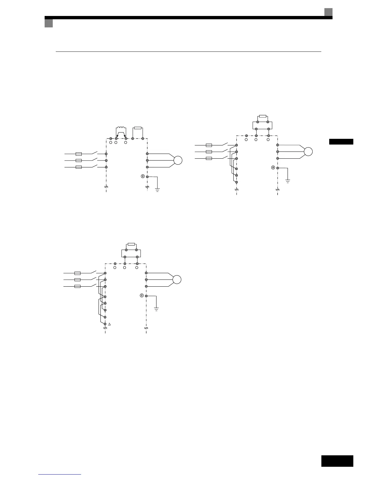
Standard Connection Diagrams
Standard Inverter connection diagrams are shown in Fig 2.4. These are the same for both 200 V Class and
400 V Class Inverters. The connections depend on the Inverter capacity.
Control power is supplied internally from the DC bus at all inverter models.
Fig 2.4 Main Circuit Terminal Connections
CIMR-L7Z23P7 to 2018 and 43P7 to 4018
Be sure to remove the short-circuit bar before connecting
the DC reactor.
CIMR-L7Z2022, 2030, and 4022 to 4055
The DC reactor is built in.
CIMR-L7Z2037 to 2055
+
1
- +
2B1 B2
R/L1
S/L2
T/L3
U/T1
V/T2
W/T3
M
3 Phase 200VAC or
400VAC
Braking
Resistor
(optional)
DC reactor
(optional)
+
1
-+
3
R/L1
S/L2
T/L3
U/T1
V/T2
W/T3
M
3 Phase 200VAC or
400VAC
CDBR Braking
Unit (optional)
Braking
Resistor (optional)
R1/L11
S1/L21
T1/L31
+
1
-+
3
R/L1
S/L2
T/L3
U/T1
V/T2
W/T3
M
3 Phase 200VAC or
400VAC
CDBR Braking
Unit (optional)
Braking
Resistor (optional)
R1/L11
S1/L21
T1/L31
r / l1
/ l2
 Loading...


