1-5
1
Component Names
Inverters of 18.5 kW or Less
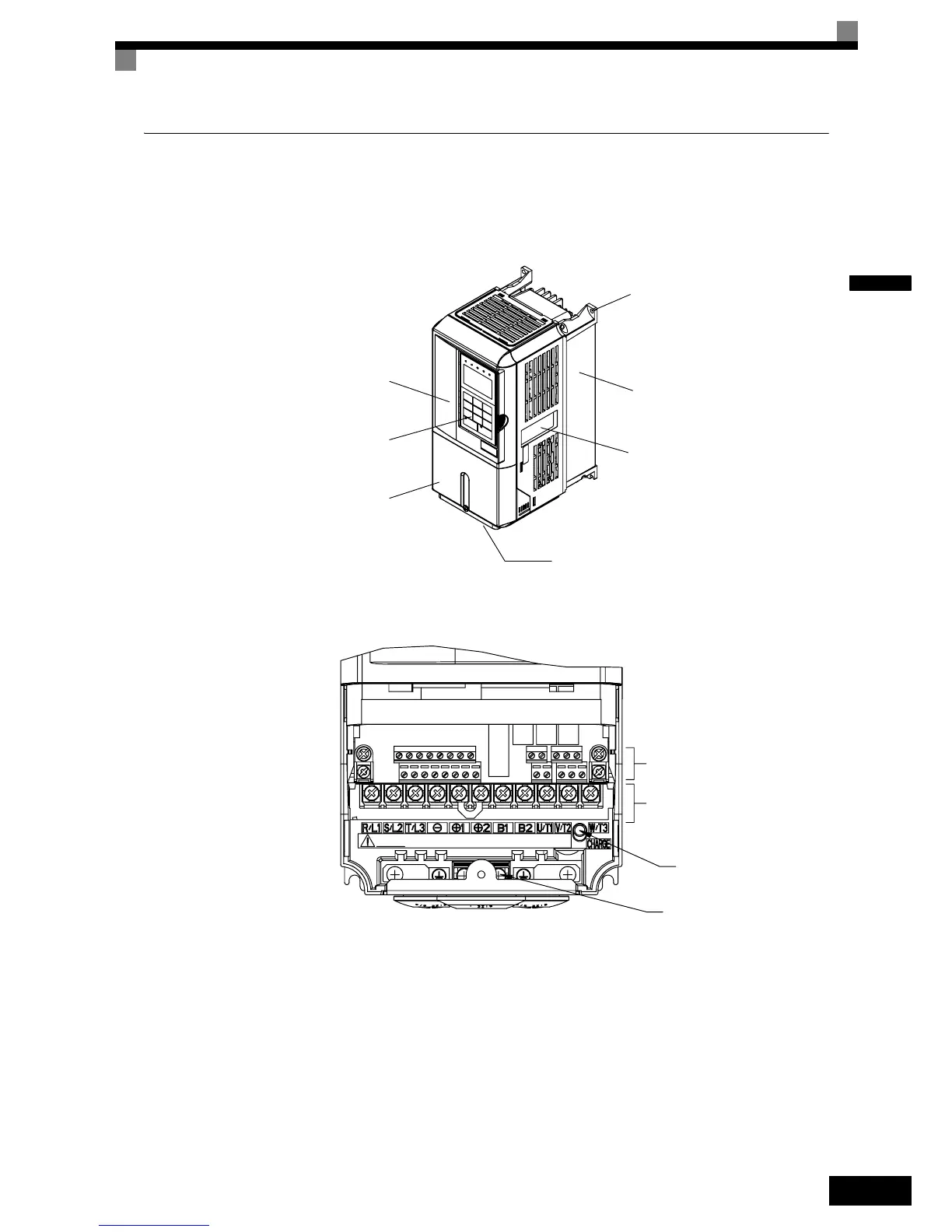
The external appearance and component names of the Inverter are shown in Fig 1.4. The Inverter with the ter-
minal cover removed is shown in Fig 1.5.
Fig 1.4 Inverter Appearance (18.5 kW or Less)
Fig 1.5 Terminal Arrangement (18.5 kW or Less)
Front cover
Digital Operator
Terminal cover
Nameplate
Heatsink
Mounting holes
Bottom Protective Cover
Control circuit terminals
Main circuit terminals
Ground terminal
Charge indicator
 Loading...


