6-59
6
Motor and V/f Pattern Setup
The L7 inverter supports 2 motor settings (main motor and door motor, E2/E4- parameters) for V/f con-
trol, Open Loop Vector and Closed Loop Vector for IM. The active motor setup can be selected by a digital
input.
Closed Loop Vector Control for PM supports 1 motor setting (main motor, E5- parameters) only.
Setting Motor Parameters for Induction Motors (Motor 1 and 2)
In order to achieve the maximum performance the V/f pattern and the motor data must be set correctly.
The number of motor parameters which can be set, depend on the selected control mode.
In the vector control methods the motor parameters can be set automatically by using the autotuning function
(refer to page 4-4, Autotuning).
However, if autotuning does not complete normally, the parameters must be set manually like described
below.
Related Parameters
Parameter
No.
Name
Factory
Setting
Change
during
Operation
Control Methods
Set by
Auto-
tuning
V/f
Open
Loop
Vector
Closed
Loop
Vector
Closed
Loop
Vector
for PM
d1-19 Motor 2 speed reference 0.00 Hz No A A A - No
E1-01 Input voltage setting
400 V
*1
No Q Q Q Q No
E3-01 Motor 2 control mode selection 0 No A A A A No
E1-04/
E3-02
Max. output frequency (FMAX) 50.0 Hz No
Q/
A
Q/
A
Q/
A
Q/
A
Yes
E1-05/
E3-03
Max. voltage (VMAX)
380.0 V
*1
No
Q/
A
Q/
A
Q/
A
Q/
A
Yes
E1-06/
E3-04
Base frequency (FA) 50.0 Hz No
Q/
A
Q/
A
Q/
A
Q/
A
Yes
E1-07/
E3-05
Mid. output frequency (FB)
3.0 Hz
*1
No A A - - Yes
E1-08/
E3-06
Mid. output frequency voltage (VB)
37.3 V
*1,*2
No
Q/
A
Q/
A
--Yes
E1-09/
E3-07
Min. output frequency (FMIN)
0.5 Hz
*2
No
Q/
A
Q/
A
AAYes
E1-10/
E3-08
Min. output frequency voltage (VMIN)
19.4 V
*1,*2
No
Q/
A
Q/
A
--Yes
E1-13 Base voltage (VBASE) 0.0 V No A A - Q Yes
E2-01/
E4-01
Motor rated current
7.00 A
*3
No
Q/
A
Q/
A
Q/
A
-Yes
E2-02
E4-02
Motor rated slip
2.70 Hz
*3
No A A A - Yes
E2-03/
E4-03
Motor no-load current
2.30 A
*3
No A A A - Yes
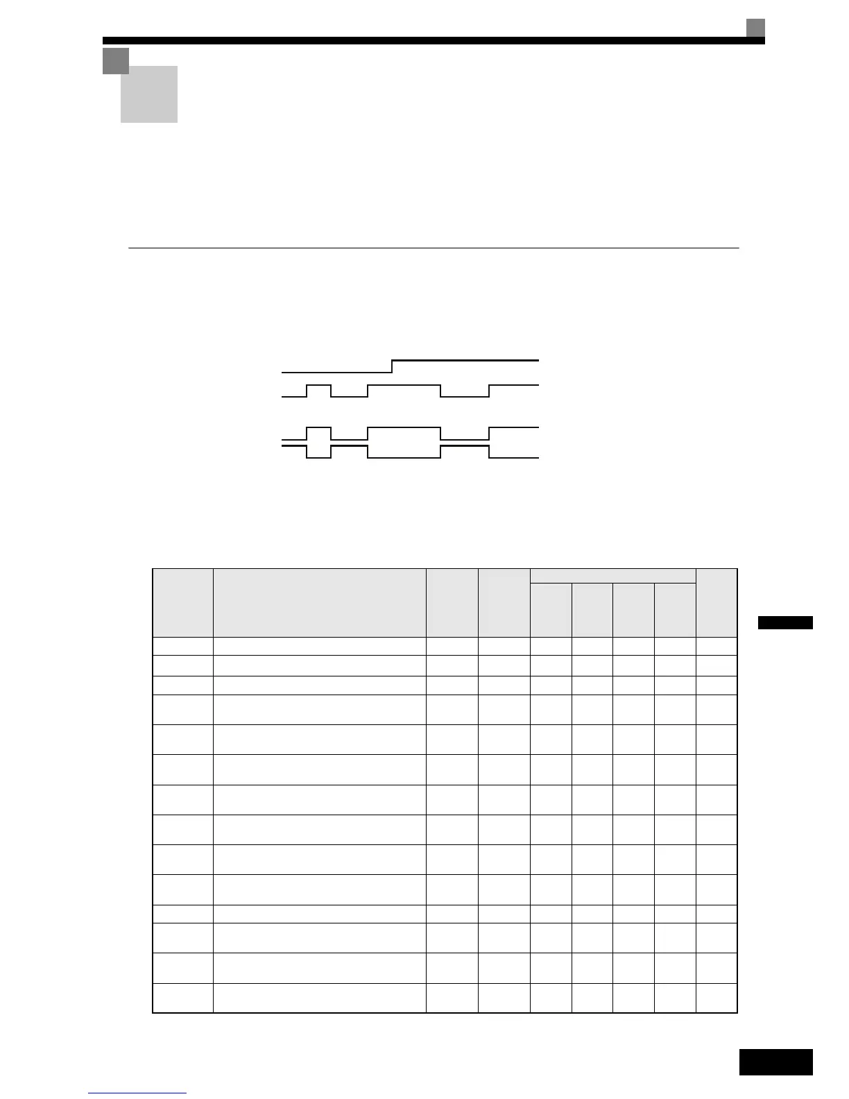
Up/Down command
Base Block Input
(Term BB & BB1)
BB Monitor 1
BB Monitor 2
 Loading...


