2-20
2
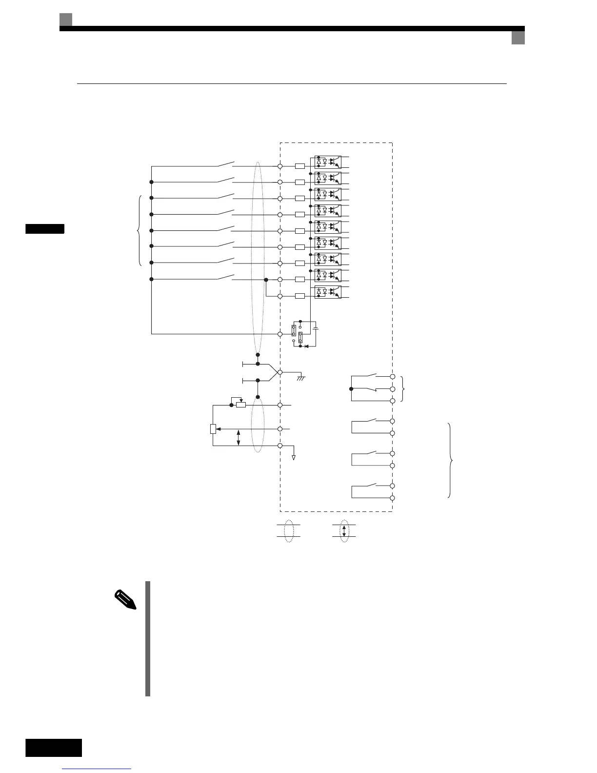
Control Circuit Terminal Connections
Connections to Inverter control circuit terminals are shown in Fig 2.12.
Fig 2.12 Control Circuit Terminal Connections
INFO
The base block circuit is a two channel circuit, i.e. always both channels (terminal BB and BB1) have to
be enabled to enable the inverter output.
Generally the terminals BB and BB1 can be linked directly at the terminals. However, if an EN81-1 con-
form one motor contactor solution is required, the recommended BB and BB1 terminal wiring depends on
the installation:
1. If the controller and inverter are mounted in the same cabinet the terminals BB and BB1 can be linked
directly at the inverter terminal board. Only one wire from the controller to the inverter base block
input is necessary.
2. If the inverter is mounted separated from the controller cabinet, two physically separated wires for the
BB and BB1 terminal should be used in order to keep redundancy in case of a fault of one of the signal
lines.
Voltage adjust-
ment
S1
S3
S2
S4
S5
S6
S7
BB
BB1
Multi function
Inputs
(Factory setting)
Forward run/stop
Reverse run/stop
Nominal Speed
Inspection Run
Intermediate Speed
Leveling Speed
Not used
Hardware Baseblock (note 2)
SC
+24V, 8mA
IP24V (24V)
CN5(NPN setting)
E(G)
MA
MB
MC
Fault contact output
250VAC, max. 1A
30VDC, max. 1A
M1
M2
M3
M5
M4
M6
Brake Command
(Factory setting)
Contactor Control
(Factory setting)
Inverter Ready
(Factory setting)
Multi-function
contact output
250VAC, max. 1A
30VDC, max. 1A
Analog input power
supply +15V, 20mA
Master speed
reference 0 to 10V
+V
A1
AC
0 V
P
2kOhm
Analog input
(Speed reference)
2kOhm
0 to 10 V
Twisted-pair
wires
Shielded
wires
Note:
1. The CN5 factory setting is NPN
2. To enable the inverter both inputs, BB and BB1 must be closed. If
only one of the inputs is closed, “BB” will be displayed in the
operator panel and the inverter will not start.
 Loading...


