6-81
6
Automatic Fault Reset
The inverter can reset faults automatically. The maximum number of resets can be selected as well as the oper-
ation mode of the fault relay.
Auto-resetable Fault codes are: UV1, GF, OC, OV, OL2, OL3, OL4, UL3, UL4, PF, LF, SE1, SE2, SE3
Related Constants.
Multi-function Digital Outputs (H2-01 to H2-03)
Working Principle
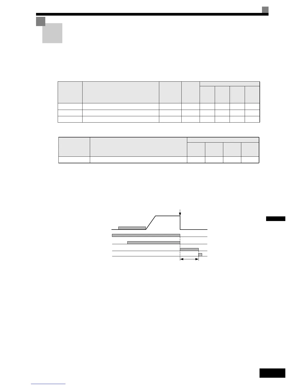
Whenever a fault occurs, the inverter output is cut and the brake is closed. A fault is output. When the auto-
matic fault reset is enabled, the fault is reset 2 seconds after the Up/Down signal has been removed. The
inverter can be restarted. This can be repeated for the number of times set in L5-02. The restart counter is reset
when the power supply is switched off.
Fig 6.27 Automatic Fault Reset Sequence
Fault Relay Operation
Parameter L5-02 can be used to enable or disable the fault relay (terminal MA-MB-MC) during the fault retry.
Even if the fault relay is deactivated during the retries (L5-02=0), it is operated after the number of retries set
in L5-01 has been reached.
• L5-02 = 1 enabled the fault relay.
• L5-02 = 0 disables the fault relay.
Parameter
No.
Name
Factory
setting
Change
during
operation
Control Methods
V/f
Open
Loop
Vector
Closed
Loop
Vector
Closed
Loop
Vector
(PM)
L5-01 Number of restarts 2 No A A A A
L5-02 Restart operation selection 1 No A A A A
L5-05 UV1 auto reset selection 0 No A A A A
Setting Function name
Control Methods
V/f
Open
Loop
Vector
Closed
Loop
Vector
Closed
Loop Vec-
tor (PM)
1E Fault restart active A A A A
Up/Down
Speed
DC Injection/
Zero servo
Brake Open Command
Fault Output
Fault
Auto-Reset
The fault is reset 2 sec. After
the Up/Down signal has been
removed
 Loading...


