6-5
6
Speed Selection Sequence Using Digital Inputs
If the digital inputs are used for speed selection, the speed selection method and the speed priority depends on
the setting of parameter d1-18.
Multi-Step Speed Operation 1/2 (Binary Input) (d1-18=0/3)
If d1-18 = 0
8 preset speed steps (defined in the parameters d1-01 to d1-08) can be selected using 3 binary coded digital
inputs. The Up/Down command starts the inverter. It stops when the Up/Down command is removed.
If d1-18 = 3
7 preset speed steps (defined in the parameters d1-02 to d1-08) can be selected using 3 binary coded digital
inputs. The Up/Down command starts the inverter. It is stopped when the Up/Down command is removed or
when no speed is selected (all D/Is off).
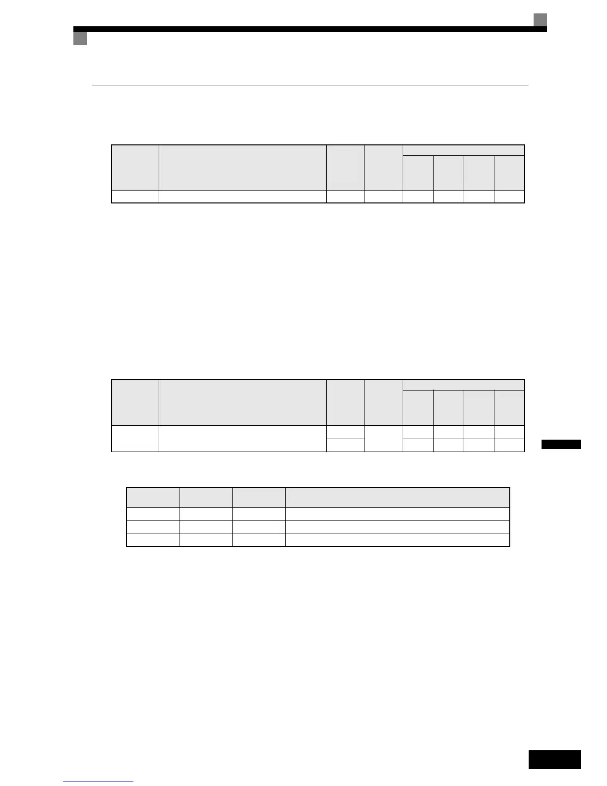
Related Parameters
Multi-function Digital Input Settings (H1-01 to H1-05) (Example)
Parameter
No.
Name
Factory
Setting
Change
during
Operation
Control Methods
V/f
Open
Loop
Vector
Closed
Loop
Vector
Closed
Loop
Vector
(PM)
d1-18 Speed Priority Selection 1 No QQQQ
Parameter
No.
Name
Factory
Setting
Change
during
Operation
Control Methods
V/f
Open
Loop
Vector
Closed
Loop
Vector
Closed
Loop
Vector
(PM)
d1-01 to
d1-08
Multi-Step speed 1 to 8 reference value
0.00 Hz
Yes
AAA -
0.00% - - - A
Ter mi na l
Parameter
Number
Set Value Details
S4 H1-02 3 Multi-step speed command 1
S5 H1-03 4 Multi-step speed command 2
S6 H1-04 5 Multi-step speed command 3
 Loading...


