5-10
5
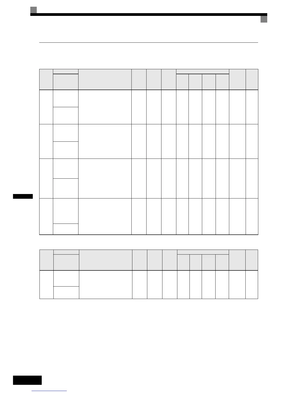
Application Parameters: b
Operation Mode Selections: b1
DC Injection Braking: b2
Param-
eter
Num-
ber
Name
Description
Setting
Range
Factory
Setting
Change
during
Opera-
tion
Control Methods
MEMO-
BUS
Register
Page
V/f
Open
Loop
Vector
Closed
Loop
Vector
Closed
Loop
Vector
(PM)
Display
b1-01
Reference
source selec-
tion
Sets the frequency reference
input method.
0:Digital Operator
1:Control circuit terminal (ana-
log input)
3:Option Card
0, 1 or
3
0 NoAAAA180H6-4
Reference
Source
b1-02
RUN com-
mand source
selection
Sets the run command input
method.
0:Digital Operator
1:Control circuit terminal (digital
multifunction inputs)
3:Option Card
0, 1 or
3
1 NoAAAA181H6-3
Run Source
b1-06
Control input
scan
Used to set the responsiveness of
the control inputs (forward/
reverse and multi-function
inputs.)
0:Fast reading
1:Normal reading (Can be used
for possible malfunction due to
noise.)
0 or 1 1 No A A A A 185H -
Cntl Input
Scans
b1-08
Run com-
mand selec-
tion in
programming
modes
Used to set an operation prohibi-
tion in programming modes.
0:Operation prohibited.
1:Operation permitted (Disabled
when Digital Operator is the
selected Run command source
(b1-02 = 0)).
0 or 1 1 No A A A A 187H -
RUN CMD at
PRG
Param-
eter
Num-
ber
Name
Description
Setting
Range
Factory
Setting
Change
during
Opera-
tion
Control Methods
MEMO-
BUS
Register
Page
V/f
Open
Loop
Vector
Closed
Loop
Vector
Closed
Loop
Vector
(PM)
Display
b2-08
Magnetic flux
compensation
volume
Sets the magnetic flux compensa-
tion as a percentage of the no-
load current.
0 to
1000
0% No - A - - 190H -
Field Comp
 Loading...


