6-72
6
PG Option Cards
To have a more precise speed control the inverter can be equipped with a PG option card for the connection of
a pulse generator. Three different PG cards can be used, the PG-B2, the PG-X2 and the PG-F2 card. Refer to
page 2-24, Option Card Models and Specifications to see details.
PG Setup
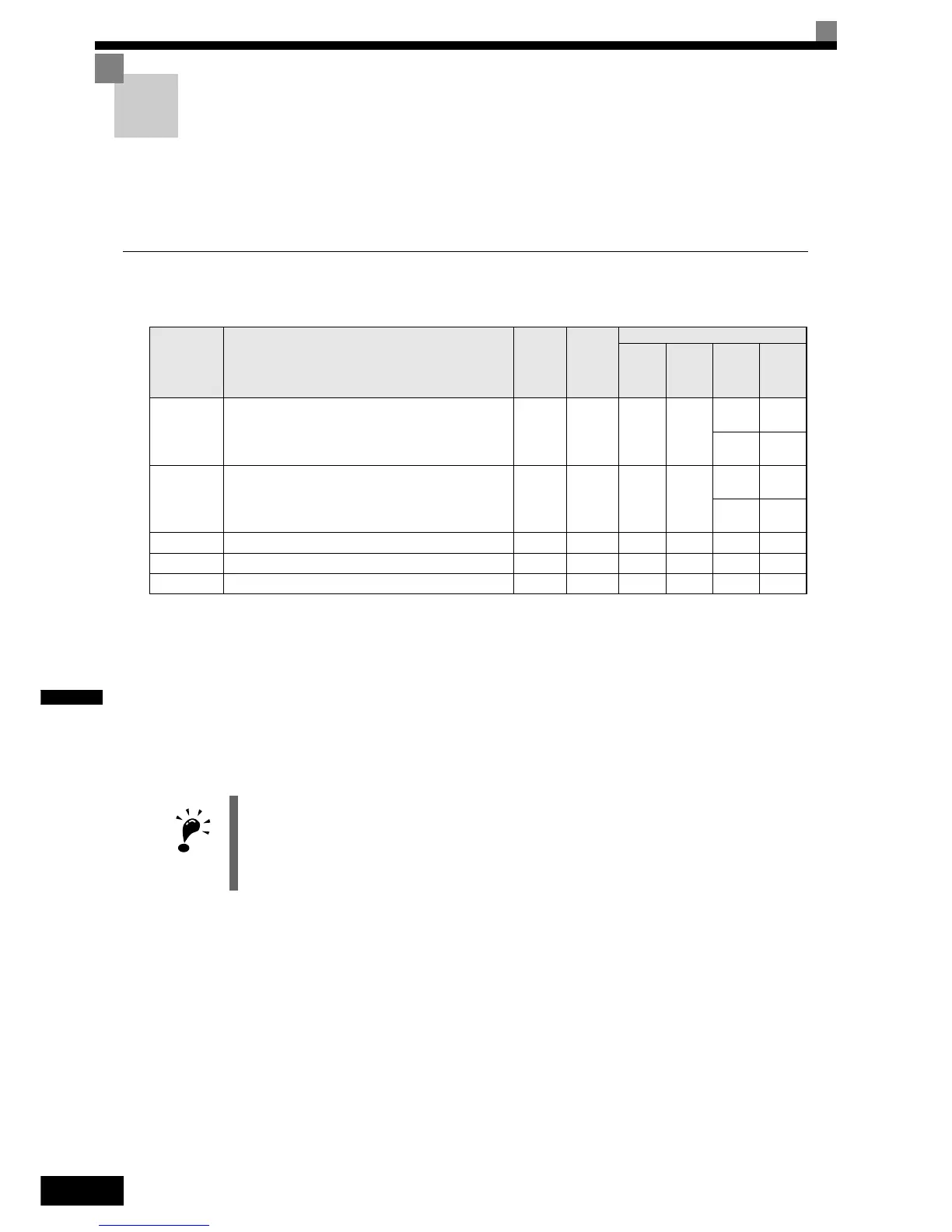
Related Parameters
Using PG Speed Control Card
There are three types of PG Speed Control Card that can be used in Closed Loop Vector control:
• PG-B2: A/B-phase pulse input, compatible with open collector outputs.
• PG-X2: A/B/Z-phase pulse input, compatible with line drivers (RS-422).
• PG-F2: Hiperface
y
/ EnDat encoder feedback.
For the mounting instructions, specifications and connection diagrams refer to page 2-24, Installing and Wir-
ing Option Cards.
Setting Number of PG Pulses (F1-01)
Set the number of PG (Pulse Generator/Encoder) pulses in pulses per revolution.
If a PG-F2 card is installed, the encoder type must be set in parameter n8-35 before the PG constant is set. The
possible set values for F1-01 depend on the n8-35 setting. The following resolutions can be set:
• for Hiperface
y
: 1024
• for EnDat: 512, 1024, 2048
Parameter
No.
Name
Factory
Setting
Change
during
Opera-
tion
Control Methods
V/f
Open
Loop
Vector
Closed
Loop
Vector
Closed
Loop
Vector
(PM)
F1-01 PG constant
i
No No No
Q
1024
-
-
Q
2048
F1-05 PG rotation
i
No No No
Q
0
-
-
Q
1
F1-06 PG division rate (PG pulse monitor) 1 No No No A A
F1-21 Absolute encoder resolution 2 No No No No A
F1-22 Magnet position offset 60° No No No No A
IMPORTANT
If Open Loop Vector control for IM is used and a PG-B2/X2 card is installed, the speed detected by the
PG card is displayed in the monitor parameter U1-05. Therefore the PG constant has to be set in parame-
ter F1-01. The direction of the speed detection can be changed by parameter F1-05.
To change the U1-05 value to the internally calculated speed value remove the PG card.
 Loading...


