6-77
6
Rescue System
Using rescue operation the car can be moved to the next floor if the power supply fails. In this case the inverter
must be supplied by a UPS or a battery and the rescue operation must be enabled by a digital input (H1- =
85). The DC bus voltage during rescue operation has to be set in parameter L2-11. A light load detection func-
tion can be used to detect the light load direction for the car evacuation.
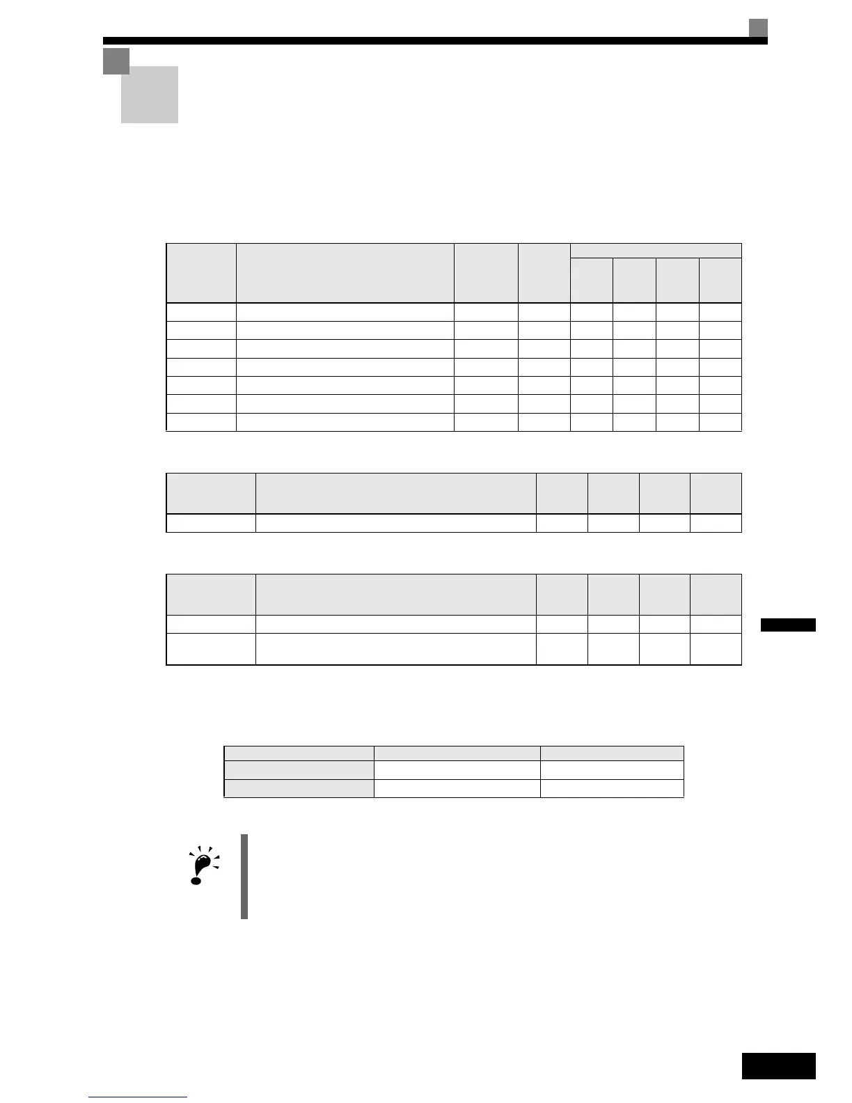
Related Parameters.
Multi-function Digital Inputs (H1-01 to H1-05)
Multi-function Digital Outputs (H2-01 to H2-03)
Rescue Operation Power Supply Ratings
The power supply to the DC bus and to the control card during rescue operation must meet the following
requirements:
Parameter
No.
Name
Factory
setting
Change
during
operation
Control Methods
V/f
Open
Loop
Vector
Closed
Loop
Vector
Closed
Loop
Vector
(PM)
d1-05 Rescue operation speed 5 Hz No A A A A
L2-11 DC bus voltage during rescue operation 0V No A A A A
S3-06 Light Load Search for rescue operation 0 No A A A A
S3-07 Light Load Search time for rescue operation 1.0 sec. No A A A A
S3-10 Light Load Search speed 3.00 Hz No A A A A
S3-11 Rescue operation torque limit 100% No - A A A
S3-24 Light load search method 0 No A A - -
Setting Function mane V/f
Open
Loop
Vector
Closed
Loop
Vector
Closed
Loop Vec-
tor (PM)
85Rescue operation command AAAA
Setting Function mane V/f
Open
Loop
Vector
Closed
Loop
Vector
Closed
Loop Vec-
tor (PM)
44Light load direction output (ON: Forward, OFF: Reverse) AAAA
45
Light load detection status (ON: Ready for detection run, OFF:
Detection in progress)
AAAA
Voltage class DC Bus Power Supply Control Power Supply
200 V 48 to 300 VDC 280 to 300 VDC
400 V 96 to 600 VDC 280 to 600 VDC
IMPORTANT
When an AC power supply (e.g. a single phase UPS like example 1 or 2 below) is used,
make sure that the rectified voltage meets the voltage range above.
 Loading...


