2-25
2
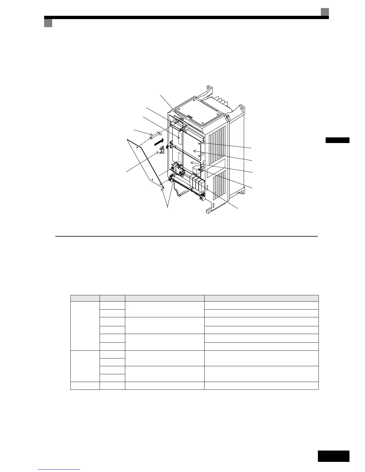
Preventing C and D Option Card Connectors from Rising
After installing an Option Card into slot C or D, insert an Option Clip to prevent the side with the connector
from rising. The Option Clip can be easily removed by holding onto the protruding portion of the Clip and
pulling it out.
Fig 2.14 Mounting Option Cards
PG Speed Control Card Terminals and Specifications
PG-B2 Option Card
Input/Output Specifications
Table 2.12 PG-B2 I/O Specifications
Terminal No. Contents Specifications
TA1
1
Power supply for pulse generator
12 VDC (±5%), 200 mA max.
2 0 VDC (GND for power supply)
3
Pulse input terminals phase A
H: +8 to 12 V (max. input frequency: 50 kHz)
4 GND pulse input phase A
5
Pulse input terminals phase B
H: +8 to 12 V (max. input frequency: 50 kHz)
6 GND pulse input phase B
TA2
1
Pulse monitor output terminals
phase A
Open collector output, 24 VDC, 30 mA max.
2
3
Pulse monitor output terminals
phase B
Open collector output, 24 VDC, 30 mA max.
4
TA3 (E) Shield connection terminal -
A Option Card mounting spacer hole
CN4
A Option Card connector
CN2
C Option Card connector
A Option Card mounting spacer
(Provided with A Option Card)
Option Clip
(To prevent raising of
C and D Option Card)
A Option Card
A Option Card mounting spacer
C Option Card mounting spacer
C Option Card
D Option Card mounting spacer
D Option Card
 Loading...


