4.18
ELECTRONIC FUEL INJECTION
9924096 - 2013 RANGER RZR XP 900 / RZR XP 4 900 Service Manual
© Copyright 2012 Polaris Sales Inc.
CRANKSHAFT POSITION SENSOR
(CPS)
Operation Overview
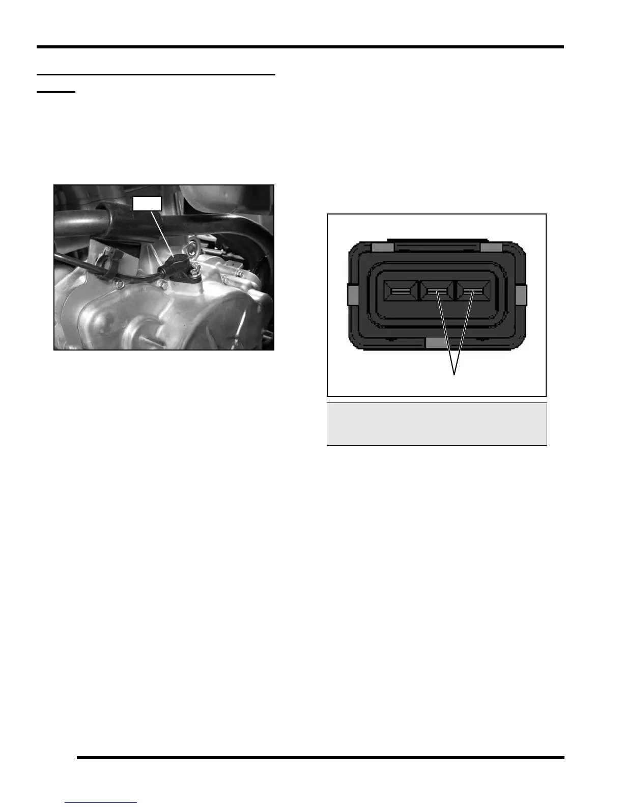
Mounted on top of the stator cover, the crankshaft position
sensor is essential to engine operation, constantly
monitoring the rotational speed (RPM) and position of the
crankshaft.
A ferromagnetic 35-tooth encoder ring with a missing tooth
is built onto the flywheel. The inductive speed sensor is
mounted 1.0 ± 0.26 mm (0.059 ± 0.010 in.) away from the
encoder ring. During rotation, an AC pulse is created
within the sensor for each passing tooth. The ECU
calculates engine speed from the time interval between
the consecutive pulses.
The encoder ring missing tooth creates an “interrupt” input
signal, corresponding to specific crankshaft position. This
signal serves as a reference for the control of ignition
timing by the ECU. Synchronization of the CPS and
crankshaft position takes place during the first two
revolutions each time the engine is started. This sensor
must be properly connected at all times. If the sensor fails
or becomes disconnected for any reason, the engine will
stop running.
CPS Test
The CPS is a sealed, non-serviceable assembly. If fault
code diagnosis indicates a problem with this sensor, test
as follows:
1. Locate the CPS harness connector above the
transmission on the RH side of the vehicle and
disconnect the harness.
2. Connect an ohmmeter between the CPS pin terminals
shown below. A resistance value of 1000
10% at
room temperature should be obtained.
3. If the resistance is correct:
• Test the main harness circuit between the sensor
connector terminals and the corresponding pin
terminals at the ECU (see wiring diagram).
• Check the sensor mounting, air gap, flywheel
encoder ring for damage or runout, and flywheel
key. Follow the “CPS Replacement” procedure to
inspect CPS and flywheel encoder ring for
damage.
4. If the resistance is incorrect, follow the “CPS
Replacement” procedure.
CPS Resistance Specification:
1000
10%
 Loading...