10.19
ELECTRICAL
10
9924096 - 2013 RANGER RZR XP 900 / RZR XP 4 900 Service Manual
© Copyright 2012 Polaris Sales Inc.
VEHICLE SPEED SENSOR
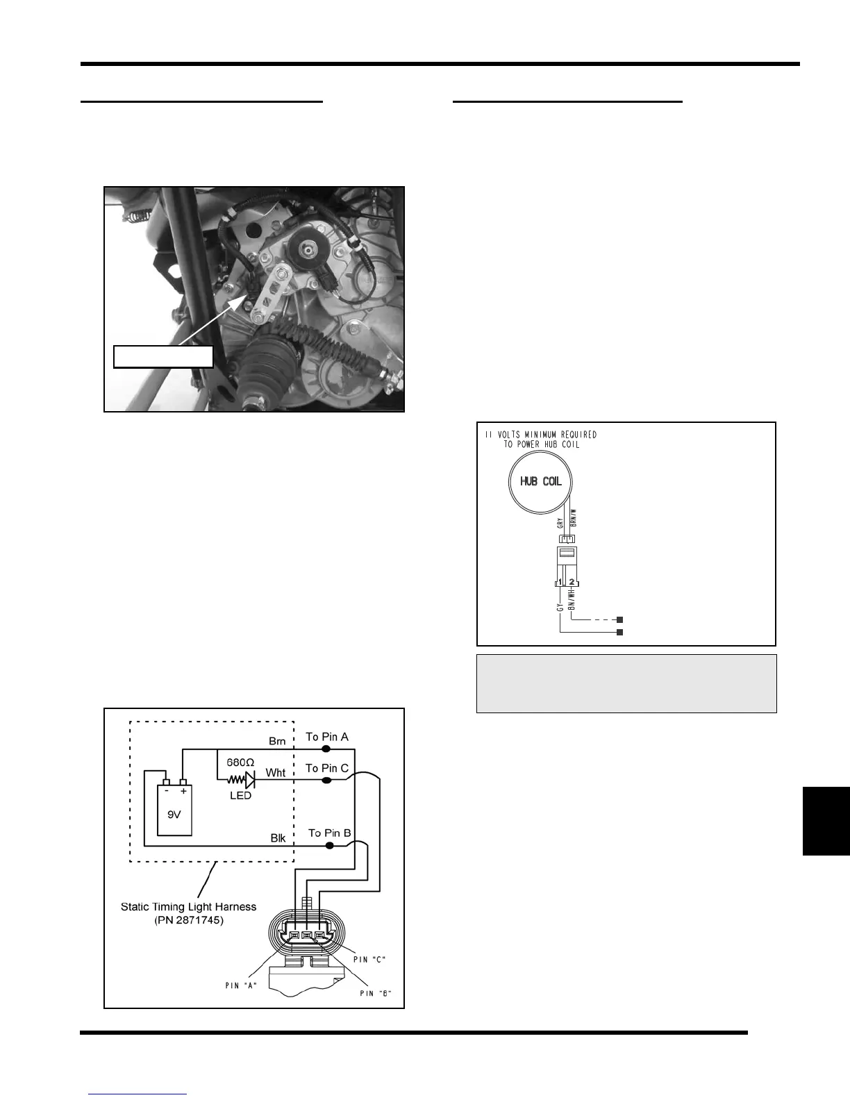
Speed Sensor Location
The speed sensor is located on the RH side of the
transmission, accessed through the rear RH wheel well.
Speed Sensor Testing
Special Tools Required:
Static Timing Light Harness (PN 2871745)
Hall Sensor Probe Harness (PN 2460761)
1. Disconnect the 3 wire harness from the speed sensor
and remove the sensor from the transmission.
2. Connect the wires from the Static Timing Light
Harness to the sensor 3 pin connector using the Hall
Sensor Probe Harness (PN 2460761).
3. Pass a screwdriver back and forth in front of the
sensor tip.
4. Be sure connections are good and 9V battery is in
good condition. If the light flashes, the sensor is good.
ALL WHEEL DRIVE COIL
Operation Overview
• When the key switch is “ON”, 12 VDC power is
present at the hub coil.
• When the AWD switch is “ON”, and if the criteria is
met, the Engine Controller provides a ground path
(brown/white wire). When this occurs the AWD
icon should display in the instrument cluster.
• The AWD system must be grounded to operate.
Diagnosing System Failures
• Verify the AWD switch is functional and that a
minimum of 11 volts is present at the hub coil.
• Verify the AWD hub coil is functional. Test the
AWD hub coil using an ohm meter. See
specifications below:
• Verify the wiring harness, wiring, connectors,
connector pins and grounds are undamaged,
clean and connect properly.
• Verify continuity of wire connections with a known
good volt/ohm meter.
IMPORTANT: Verify all wires and wiring connections
have been tested properly with a known good volt/
ohm meter before suspecting a component failure.
80% of all electrical issues are caused by bad/failed
connections and grounds.
AWD Hub Coil Resistance:
24
± 5%
Test Resistance Test Resistance
Readings should be: Readings should be:
GY to BN/WH: ~ 24 OhmsGY to BN/WH: ~ 24 Ohms
GY to Ground: No ConnectionGY to Ground: No Connection
 Loading...