
Do you have a question about the Polaris xp 2013 eps and is the answer not in the manual?
| Brand | Polaris |
|---|---|
| Model | xp 2013 eps |
| Category | Utility Vehicle |
| Language | English |
Details on model number designation, engine designation, and VIN.
Information on where to find the VIN and engine serial numbers on the vehicle.
Covers publication numbers and information on replacement keys.
Lists and describes specialized tools required for servicing the vehicle.
Provides detailed specifications for various models of the vehicle.
Includes conversion tables and torque specifications for bolts.
Overview of inspection, adjustment, and lubrication intervals for vehicle maintenance.
Details daily inspections, frame checks, and component inspections.
Procedures for servicing the fuel tank, lines, pump, and air intake system.
Covers engine oil level checks, oil and filter changes, and breather hose inspection.
Information on coolant level, strength, pressure tests, hoses, radiator, and thermostat.
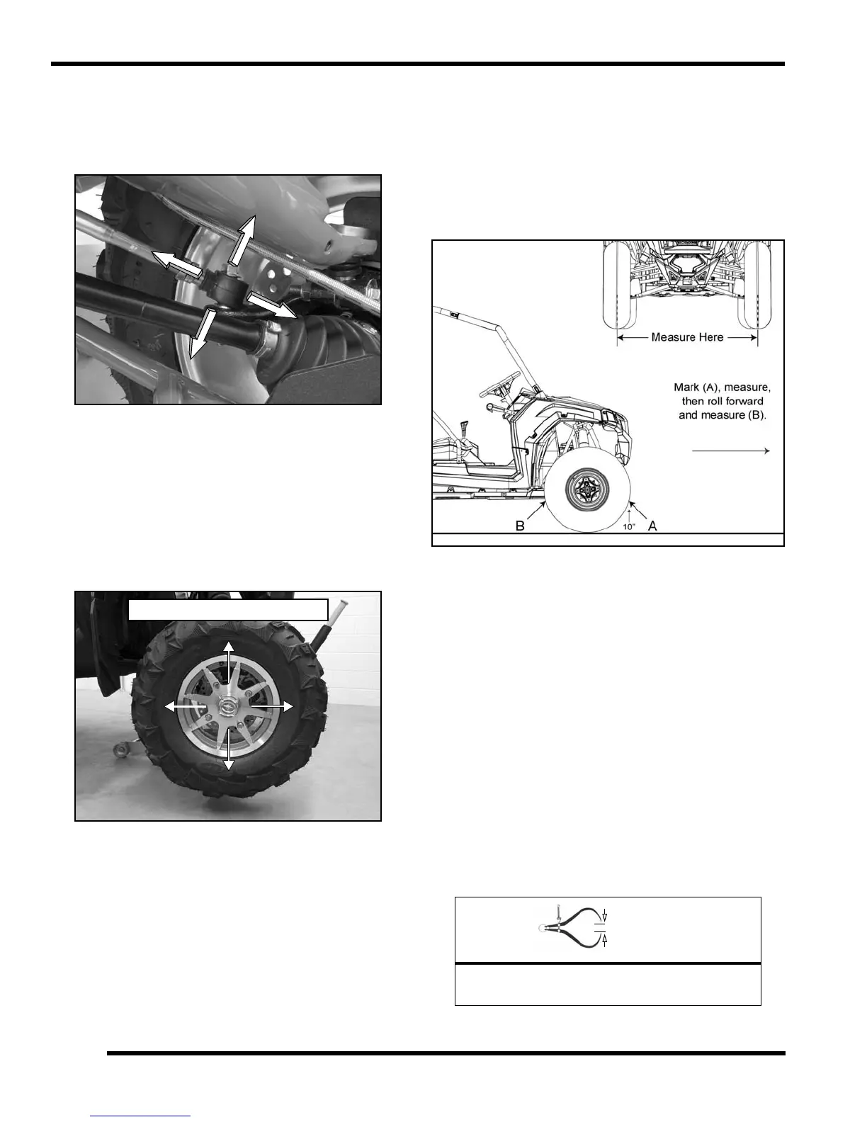
Service procedures for PVT system, drive shaft boots, wheels, and tires.
Covers battery maintenance, removal, installation, and testing.
Inspection and adjustment of steering components and wheel alignment.
Details on spring preload and shock compression adjustments for FOX™ shocks.
Procedures for adjusting spring preload and shock compression on Walker Evans™ shocks.
Inspection and service for brake fluid, pads, discs, hoses, and fittings.
Adjustment and inspection procedures for the parking brake system.
Covers special tools and engine lubrication specifications.
Details cooling system specifications, pressure tests, and component procedures.
Information on accessible components, top-end service, and engine removal/installation.
Procedures for valve cover, camshaft, and cylinder head removal and inspection.
Covers stator cover, water pump, flywheel, and starter removal/inspection.
Includes special tools, EFI service notes, and system exploded views.
Details on fuel tank exploded view, fuel flow, and line removal/installation.
Covers principal components, EFI operation, and initial priming procedures.
Information on ECU operation, service, and replacement procedures.
Details MAQS operation, testing, and replacement.
Covers CPS operation, testing, and replacement procedures.
Explains IAC operation, testing, and replacement.
Covers ECT operation, testing, and replacement.
Details throttle body operation, service, and removal.
Covers injector operation, troubleshooting, testing, and replacement.
Explains fuel pump operation, testing, and replacement.
Covers ignition coil operation, HT lead replacement, and testing.
Information on instrument cluster trouble code display and diagnostic tables.
Lists torque values for various chassis and suspension components.
Lists special tools required for body, steering, and suspension service.
Details assembly and removal procedures for the RZR XP cab frame.
Provides assembly and removal procedures for the RZR XP 4 cab frame.
Procedures for removing seats, engine service panel, bumpers, and hood.
Exploded views and procedures for steering system components.
Covers EPS system operation, troubleshooting, and component removal.
Details removal and replacement procedures for front A-arms.
Procedures for removing and installing ball joints.
Covers stabilizer bar linkage and stabilizer bar removal/installation.
Details removal and installation of rear radius rods.
Procedures for trailing arm removal, installation, and bearing replacement.
Information on shock removal, installation, and replacement.
Exploded views of FOX™ 2.0 ‘Piggyback’ shocks.
Covers shock rebuild information and disassembly procedures.
Details shock service, rebuild, and disassembly for Walker Evans™ shocks.
Lists tools and supplies needed for PVT system service.
Provides torque values for PVT system fasteners.
Explains general operation, drive clutch, driven clutch, and drive belt.
Covers PVT covers, ducting, disassembly, and assembly procedures.
Details belt removal, inspection, and installation procedures.
Exploded view and disassembly/inspection of the drive clutch.
Covers driven clutch disassembly, bushing service, and assembly.
Troubleshooting guide for common PVT system issues.
Lists special tools required for final drive service.
Provides torque values for wheel hub and final drive components.
Details bearing carrier inspection, removal, replacement, and installation.
Procedures for front drive shaft removal and installation.
Covers front and rear propshaft removal and installation.
Exploded view and operation of the front gearcase and AWD system.
Details rear bearing carrier inspection, removal, replacement, and installation.
Procedures for rear drive shaft removal and installation.
Handling tips and procedures for outer CV joint and boot replacement.
Exploded views of front and rear wheel hubs.
Covers torque specifications, special tools, lubrication, and mounting values.
Details removal and installation procedures for the shift lever.
Covers inspection and adjustment procedures for the shift cable.
Step-by-step instructions for removing the transmission assembly.
Procedures for installing the transmission assembly.
Covers transmission disassembly, inspection, and assembly.
Details differential operation and components for international models.
Checklist for diagnosing shifting difficulties and transmission problems.
Exploded view of the transmission for reassembly reference.
Provides standard and service limit measurements for brake system components.
Lists torque values for brake system fasteners.
Important notes for maintaining proper brake system function and pad life.
Guide to diagnosing and resolving brake noise issues.
Explains the function and components of the hydraulic brake system.
Exploded views of the brake system for RZR XP and RZR XP 4 models.
Covers master cylinder removal, installation, and brake pedal lever service.
Procedure for bleeding brakes and changing brake fluid.
Details parking brake exploded view, inspection, and cable adjustment.
Procedures for parking brake caliper removal, disassembly, and new pad installation.
Details front brake pad removal, inspection, and assembly.
Procedure for rear brake pad removal, inspection, and assembly.
Covers rear brake pad removal, inspection, and assembly for RZR XP 4.
Details disc inspection, runout measurement, and disc replacement.
Covers rear brake disc inspection and replacement procedures.
Troubleshooting common brake issues like squeal, poor performance, and overheating.
Includes special tools and important electrical service notes.
Overview of the instrument cluster, display functions, and diagnostic mode.
Details testing and replacement for various switches and controls.
Break-out diagram for the cooling system and fan control circuit testing.
Information on EFI component testing and fuel sender testing.
Overview of fuse box operation and detailed fuse/relay assignments.
Testing procedures for current draw and charging system performance.
Covers battery specifications, general information, and testing procedures.
Troubleshooting for starter motor issues and voltage drop tests.
Details EPS operation, diagnosing, and troubleshooting procedures.