Home
Ricoh
All in One Printer
G133
Ricoh G133 User Manual
4
of 1
of 1 rating
993 pages
Give review
Manual
Specs
To Next Page
To Next Page
To Previous Page
To Previous Page
Loading...
Paper Feed
SM 3-99
G133
Repla
cement
Adjustment
7.
Paper exit sensor [F] (
x 1, hook)
3.11.13
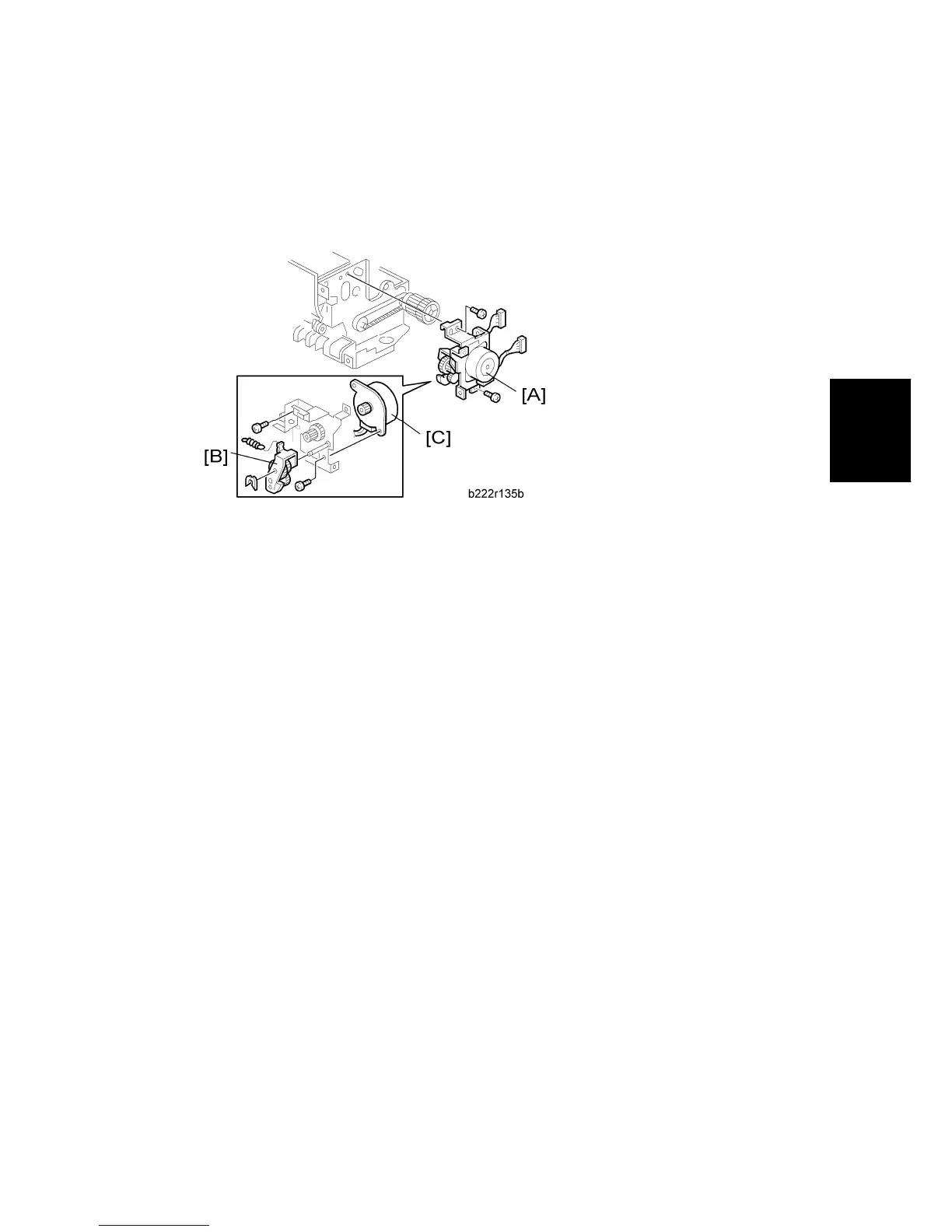
JUNCTION GATE 1 MOTOR
1.
Paper exit unit (
"p.3-3 "Paper Exit Unit"")
2.
Junction gate 1 motor bracket [A] (
x 2)
3.
Gear bracket [B] (
x 1, spring x 1)
4.
Junction gate 1 motor [C] (
x 2)
196
198
Table of Contents
Table of Contents
13
Default Chapter
1
Service Manual
1
Read this First
25
Important Safety Notices
25
Installation
29
Installation Requirements
31
Environment
31
Machine Level
31
Machine Space Requirements
32
Power Requirements
32
Optional Unit Combinations
33
Controller Options
33
Machine Options
33
Printer Installation
35
Installation Flow Chart
35
Power Socket for Peripheral
35
Installation Procedure
37
Unpacking
37
Installing the Toner
41
Loading Paper
41
Turning Power on
43
Printing the Test Page
44
Selecting the Panel Display Language
44
Meter Click Charge
45
Settings Relevant to the Service Contract
45
Moving the Machine
48
Transporting the Machine
48
Bridge Unit (B227)
49
Component Check
49
Installation Procedure
52
1000-Sheet Booklet Finisher (B793)
53
Accessory Check
53
Installation Procedure
54
Punch Unit (B807)
58
Component Check
58
Installation Procedure
59
3000-Sheet Finisher (B805)
64
Accessory Check
64
Installation Procedure
65
Support Tray Installation
68
Punch Unit (B702)
69
Component Check
69
Installation Procedure
73
Tray Heater (Standard Tray)
73
Installation Procedure
74
Tray Heater (Optional Tray)
74
For Installing the Tray Heater in the B800 (Two-Tray Paper Feed Unit)
75
For Installing the Tray Heater in the B801 (LCT)
77
For Installing the Tray Heater in the G832 (Paper Tray Unit)
80
Controller Options
84
I/F Card Slots
84
Overview
84
SD Card Slots
84
Overview
85
Sd Card Appli Move
85
Move Exec
86
Undo Exec
86
Before You Begin the Procedure
87
Data Overwrite Security Unit Type G (G874)
87
Seal Check and Removal
87
Installation Procedure
88
Preventive Maintenance
91
User Maintenance Items
93
Mainframe
93
Replacement Items
93
Service Maintenance Items
94
1000/3000-Sheet (Booklet) Finisher
94
Cleaning Items
94
Mainframe
94
Optional Units
94
Paper Tray Unit/ Two-Tray Paper Feed Unit/ LCT
94
1000/3000-Sheet (Booklet) Finisher Punch Kit
95
Replacement and Adjustment
97
Beforehand
99
Replacement and Adjustment
99
Special Tools
100
Image Adjustment
101
Adjustment Procedure
101
Adjustment Standard
101
Image Area
101
Leading Edge
101
Paper Registration Standard
101
Registration
101
Side to Side
101
Erase Margin Adjustment
102
Color Registration
103
Line Position Adjustment
103
Gamma Adjustment
104
Summary
104
Adjustment Procedure
105
Exterior Covers
108
Front Door
108
Left Cover
109
Rear Cover
109
Right Rear Cover
110
Top Right and Rear Cover
110
Operation Panel
111
Output Tray
111
Paper Exit Cover
111
Ozone Filter
112
Ozone Filter for Charge Unit
112
Ozone Filter for IH Inverter
113
Laser Optics
114
Caution Decal Location
114
Laser Optics Housing Unit
114
Before Removing the Old Laser Optics Housing Unit
115
Preparing the New Laser Optics Housing Unit
115
Recovery Procedure for no Replacement Preparation of Laser Optics Housing Unit
116
Removing the Old Laser Optics Housing Unit
117
After Installing the New Laser Optics Housing Unit
118
Installing a New Laser Optics Housing Unit
118
Polygon Mirror Motor and Drive Board
120
Shutter Motor
121
Image Creation
124
Pcu
124
Second Duct Fan
125
Third Duct Fan
126
When Reinstalling the Second Duct Fan
126
Toner Pump Unit
127
When Reinstalling the Third Duct Fan
127
When You Install the New Toner Pump Unit
130
Toner End Sensor
133
Image Transfer
134
Image Transfer Belt
134
Image Transfer Belt Unit
134
When Reinstalling the Image Transfer Belt
138
Paper Transfer
140
Paper Transfer Roller Unit
140
Paper Transfer Unit
140
High Voltage Supply Board - Discharge Plate
142
ID Sensor Board
142
Cleaning for ID Sensors
143
After Installing a New ID Sensor Unit/Board
144
Temperature and Humidity Sensor
144
Drive Unit
145
Gear Unit
146
Adjustment after Replacing the Gear Unit
152
Psu
152
Registration Motor
152
When Installing the Drive Unit
152
Paper Feed Motor
153
Drum/Development Motor-K
154
Drum/Development Motors for M, C, and y
154
PSU Bracket
154
Fusing/Paper Exit Motor
155
Itb Drive Motor
155
Image Transfer Belt Contact Motor
156
Paper Transfer Contact Motor
156
Duplex Inverter Motor
157
Duplex/By-Pass Motor
158
Toner Transport Motor
159
Toner Collection Unit
160
Paper Feed Clutches
161
Development Clutch-Y
163
Development Clutches for M and C
164
Development Clutch-K
165
Fusing
166
Fusing Lamp
166
Fusing Unit
166
Pressure Roller and Pressure Roller Bearing
168
When Re-Installing the Pressure Roller
171
Ferrite Roller Gear
173
Fusing Roller Bushing and Tension Roller Bushing
173
Tension Roller
174
When Re-Installing the Fusing Roller Bushing and Tension Roller Bushing
174
Fusing Belt, Heating Roller, Heating Roller Bushing and Fusing Roller
175
When Re-Installing the Tension Roller
175
When Re-Installing the Fusing Belt, Heating Roller, Fusing Roller and Heating Roller Bushing
177
Lubricant Roller and Cleaning Roller
178
Lubricant Roller Bushing
178
Heating Roller Thermistor
179
Pressure Roller Thermostat
179
Fusing Roller One-Way Clutch and Idle Gear
180
Pressure Roller Thermistor
180
Fusing Fan
181
When Re-Installing the Idle Gear
181
Paper Exit Fan
182
When Installing the Fusing Fan
182
Ih (Induction Heating) Inverter Fan
183
Thermopile
183
When Installing the IH Inverter Fan
183
When Installing the Paper Exit Fan
183
Fusing Belt Sensor and Ferrite Roller Hp Sensor
184
Ih Coil Fan
185
Ih Coil Unit
186
Paper Feed
188
Paper Feed Unit
188
Pick-Up, Feed and Separation Rollers
188
Tray 1 and Tray 2
188
Tray Lift Motor
189
Vertical Transport, Paper Overflow, Paper End and Paper Feed Sensor
189
By-Pass Paper Size Sensor Switch
190
Registration Sensor
190
By-Pass Bottom Tray
191
When Reinstalling this Switch
191
By-Pass Paper End Sensor
193
By-Pass Pick-Up, Feed and Separation Roller, Torque Limiter
194
By-Pass Feed Clutch
195
Paper Exit Unit
195
Fusing Exit, Paper Overflow, Junction Paper Jam and Paper Exit Sensor
196
Junction Gate 1 Motor
197
Duplex Unit
198
Duplex Door Sensor
199
Duplex Entrance Sensor
199
Duplex Unit
199
Duplex Exit Sensor
200
Electrical Components
201
Controller Box Right Cover
201
Controller Unit
201
Controller Box
202
When Opening the Controller Box
202
When Removing the Controller Box
202
Iob (In/Out Board)
204
When Installing the New Egb
205
Itb Power Supply Board
206
PSU Board
206
High Voltage Supply Board
207
High Voltage Supply Board Bracket
207
Controller Board
208
Ih Inverter
208
When Installing the New Controller Board
209
Hdd
210
Hdd Fan
210
When Installing the HDD Fan
210
Disposal of HDD Units
211
NVRAM on the Controller
212
NVRAM on the EGB
212
Nvram Replacement Procedure
212
When Installing a New NVRAM
213
Troubleshooting
215
Process Control Error Conditions
217
Developer Initialization Result
217
Process Control Self-Check Result
218
Vsg Adjustment Result
221
Line Position Adjustment Result
222
Service Call Conditions
224
SC Code Classification
225
Sc Table
228
Sensors
272
Blown Fuse Conditions
318
Power Supply Unit
318
Service Program Mode
323
Entering the Service Mode
323
Service Mode Operation
323
Accessing the Required Program
324
Display on the Control Panel Screen
324
Exiting Service Mode
324
Inputting a Value or Setting for a Service Program
324
Bit Switch Programming
326
Service Mode Table
327
Controller Service Mode
327
Engine Service Mode
333
Sp1-XXX (Feed)
333
Sp2-XXX (Drum)
355
Sp3-XXX (Process)
476
Sp5-XXX (Mode)
521
Sp6-XXX (Peripherals)
557
Sp7-XXX (Data Log)
563
Sp8-XXX: Data Log
593
Sp9-XXX: Others
618
Input Check Table
623
Table 1: Paper Height Sensor
628
Table 2: Paper Size Switch (Tray)
628
Table 3: Paper Size (By-Pass Table)
629
Output Check Table
636
Sheet Finisher
648
Test Pattern Printing
650
Firmware Update
652
Type of Firmware
652
Before You Begin
653
File Arrangement
653
Updating Firmware
653
Update Procedure
654
Error Handling
655
Nvram Data Upload/Download
656
Power Failure
656
Uploading Nvram Data
656
Downloading Nvram Data
657
Address Book Upload/Download
658
Error Message Table
659
Handling Firmware Update Errors
659
Controller Self-Diagnostics
664
Using the Debug Log
665
Switching on and Setting up Save Debug Log
665
Debug Log Codes
668
Retrieving the Debug Log from the Hdd
668
Sp5857-015 Copy Sd Card-To-Sd Card: any Desired Key
668
Sp5857-016 Create a File on Hdd to Store a Log
668
Sp5857-017 Create a File on Sd Card to Store a Log
669
Dip Switches
670
Paper Path
674
Drive Layout
675
Board Structure
677
Printing Process
678
Potential Control
680
Process Control Self Check
680
Process Control Self Check Procedure
682
Toner Density Adjustment Mode
684
Toner Supply Control
685
Toner Supply Control Modes
685
Toner Near End/Toner End Detection
686
Laser Exposure
688
Optical Path
689
Laser Synchronizing Detectors
690
Ld Safety Switch
691
Automatic Line Position Adjustment
692
Summary of each Adjustment
692
Adjustment Conditions
693
ID Sensors
695
Main Scan Skew Adjustment
695
Shutter Mechanism
696
Pcu (Photo Conductor Unit)
697
Around the Drum
698
Drum Drive
698
Phase Control Mechanism
698
Drum Charge and Quenching
699
Drum Cleaning
700
Development Operation
701
Developer Agitation
702
Development Bias
703
Toner Supply
705
Toner Near End Detection
706
Toner Supply from Toner Bottle to Toner Attraction Pump
706
Toner Supply Mechanism
706
Toner Supply from Toner Attraction Pump to Development Unit
707
Rfid (Radio Frequency ID)
708
Toner Cartridge
708
Waste Toner Collection
709
From Image Transfer Belt Unit
709
From Pcu
709
Toner Collection Path and Drive
709
Toner Collection Bottle Set/ Near-Full/ Full
710
Used Toner Distribution Mechanism
710
Image Transfer and Paper Separation
712
Itb (Image Transfer Belt) Drive
712
Itb Current
714
Transfer Belt Cleaning
715
Itb (Image Transfer Belt) Contact
716
Transfer Belt Sensor
717
Paper Transfer and Separation
718
Ptr (Paper Transfer Roller) Drive
718
Ptr (Paper Transfer Roller) Contact and Separation
719
Drive – Tray 1, Tray 2, and By-Pass Tray
722
Tray 1 and Tray
722
Paper Pick-Up
723
Paper Lift – Trays 1 and
724
Paper Feed Line Speed
728
Tray Lock at the Front
728
Tray Lock Mechanism
728
Tray Lock at the Rear
729
By-Pass Paper Separation
730
Paper Dust Collection
730
By-Pass Paper Size Detection
731
Belt and Rollers
733
Fusing Unit Drive
733
Lubricant Mechanism
733
Basic Ih System
734
Ih (Induction Heating) System
734
Paper Size Correction
734
Pressure Release Mechanism
735
Fusing Temperature Control
736
Fusing Temperatures
737
Overheat Protection
742
Cpm down Control
743
Cpm down System
743
Energy Saver Modes
743
Level 1 Energy Saver Mode
743
Fusing Unit, Image Transfer Belt Unit
744
Level 2 Energy Saver Mode
744
Pcu, Development Unit
744
Junction Gate Mechanism
746
To the Duplex Unit
747
Duplex Drive
749
Inverter Mechanism
750
Duplex Operation
751
Controller Functions
753
Hard Disk
755
General Specifications
759
Main Frame
759
Supported Paper Sizes
764
Paper Exit
766
Sheet Booklet Finisher
769
Software Accessories
773
Printer Drivers
773
Utility Software
773
Machine Configuration
775
Optional Equipment
778
Paper Tray Unit (One-Tray)
778
Two-Tray Paper Feed Unit
778
Large Capacity Tray
779
Punch Unit for 3000-Sheet Finisher
781
Sheet Booklet Finisher & Punch Unit
782
Bridge Unit
783
B227
789
Bridge Unit Control Board
791
Bridge Unit Drive Motor
792
Tray Exit Sensor
793
Relay Sensor
794
Mechanical Component Layout
795
Electrical Component Layout
797
Electrical Component Descriptions
798
B793
805
Upper Covers
808
Main Body
810
Proof Tray Exit / Full Sensor
811
Finisher Entrance Sensor
812
Shift Tray Exit Sensor
813
Shift Tray Motor
814
Lower Transport Motor
816
Shift Motor
817
Staple Folder Unit
818
Folder Unit
819
Folder Unit Exit Sensor
820
Folder Unit Entrance Sensor
821
Main Board
832
Detailed Section Descriptions
834
Mechanical Component Layout
834
Drive Layout
835
Electrical Component Layout
836
Electrical Component Descriptions
840
Junction Gates
845
Proof Tray
846
Shift Tray
847
Up/Down Motion
847
Side-To-Side Motion
848
Booklet Tray
849
Jogger Unit
852
Exit Guide Plate, Paper Feed out
853
Stapler Unit Movement
854
Stacking for Booklet Stapling
855
X 14 (Legal) or Shorter
855
Longer than 8.5 X 14 Inches
856
Moving the Stack to the Folding Position
858
Fold Plate
859
Fold Rollers
860
Punch Unit
861
Paper Position Detection
863
Punch Unit Movement
864
Punch Selection and Firing
864
Punch Hopper Mechanism
865
B800
871
Default Chapter
880
Component Layout
880
Paper Size Detection
883
Paper Height Detection
886
Read this First
891
Safety and Symbols
891
Replacement Procedure Safety
891
Symbols Used in this Manual
891
1 Replacement and Adjustment
895
Rear Cover
898
Tray Motor
899
Main Board
900
Stack Transport Clutch
901
2 Detailed Descriptions
905
Electrical Component Layout
906
Paper Amount Detection
912
Paper Stack Transport
914
Booklet Finisher Sr3020/ Finisher Sr3030 B804/B805
917
1 Replacement and Adjustment
921
Covers
921
Exterior Covers
921
Upper Tray, End Fence
922
Main Unit
923
Upper Tray Limit Sensor, Limit Switch
923
Positioning Roller
924
Proof Tray Exit Sensor
924
Upper Tray Height Sensors
925
Exit Guide Plate, Upper Tray Exit Sensor
926
Proof Tray Full Sensor
926
Finisher Entrance Sensor
927
Pre-Stack Tray Exit Sensor
927
Stapler Unit
928
Corner Stapler
928
Positioning Roller
929
Fold Unit
930
Fold Unit Entrance Sensor
932
Fold Unit Exit Sensor
932
Stack Present Sensor
933
Folding Horizontal Skew Adjustment (for B804 Only)
934
Fold Vertical Skew Adjustment (for B804 Only)
937
Booklet Stapler Unit
939
Booklet Stapler
939
Booklet Stapler Motor
939
2 Detailed Section Descriptions
942
Component Layout
942
General Layout
942
Lower Tray
943
Electrical Components
944
Summary of Electrical Components
948
Drive Layout
958
Junction Gates
960
Proof Mode
960
Shift Mode
960
Staple Mode
961
Pre-Stacking
962
Tray Movement Mechanism
964
Upper Tray
964
Lower Tray (B804 Only)
966
Corner Stapling
969
Stacking and Jogging
969
Stapler Movement
970
Corner Stapling
972
Booklet Stapling (B804 Only)
973
Booklet Pressure Mechanism
973
Booklet Stapling and Folding
974
Booklet Stapling and Folding Mechanisms
980
Upper Tray Output
983
Feed out
983
Feed out Stacking
984
Punch Unit B702 (for B804/B805)
985
Overview of Operation
985
Punch Mechanisms
987
Punch Hopper Mechanism
990
Finisher Jam Detection
992
4
Based on 1 rating
Ask a question
Give review
Questions and Answers:
Need help?
Do you have a question about the Ricoh G133 and is the answer not in the manual?
Ask a question
Ricoh G133 Specifications
General
Brand
Ricoh
Model
G133
Category
All in One Printer
Language
English
Related product manuals
Ricoh G179
682 pages
Ricoh G104
601 pages
Ricoh G147
496 pages
Ricoh G065
278 pages
Ricoh GR-C1
1207 pages
Ricoh Gestetner 5430
128 pages
Ricoh Gestetner MP 4001
81 pages
Ricoh SP 150w
102 pages
Ricoh MP C3004
2154 pages
Ricoh Pro 8300S
188 pages
Ricoh Aficio MP C2000
236 pages
Ricoh Aficio SP 100SU e
76 pages

 Loading...