Laser Exposure
SM 6-19 G133
Detailed
Descriptions
count for one particular beam varies from normal, the LD clock frequency for that beam is
adjusted.
If the board at the end position is defective, the clock frequency cannot be adjusted. At this
time, you must disable the detection feature with SP2-186-1.
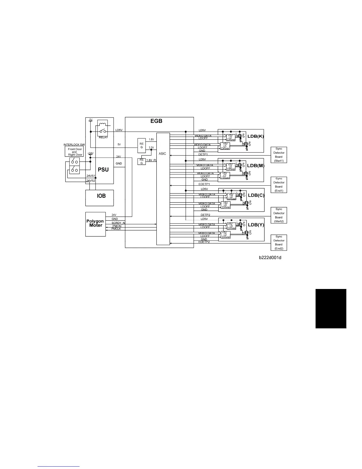
6.3.4 LD SAFETY SWITCH
A relay on the PSU ensures technician and user safety. It also prevents the laser beam
from turning on during servicing. This relay turns off when the front cover, upper left cover,
or right door is opened. At this time it cuts the power (+5V) supplied to the LD board for
each color through the EGB.
Two safety switches are turned on or off by the front door or right door, and this opens the
relay.
PMAC: Precise Pulse Modulation ASIC on C-MOS technology
LDB: LD Drive Board (included in the LD Unit)
Error Messages
Along with other switches, the LD safety switches help show error messages related to
external covers. When one or more covers are open, the messages, “Cover is open.” and
“Close the indicated cover,” show with a diagram. The diagram shows which cover is open.

 Loading...