Process Control
SM 6-11 G133
Detailed
Descriptions
ID sensor until its output when reading the bare transfer belt (known as VSG) is as follows.
VSG = 4.0 ± 0.5 Volts
This calibration compensates for the transfer belt’s condition and the ID sensor condition.
For example, dirt on the surface of the belt or ID sensor.
VSG adjustment is always done during initial process control. But, at other times, it is only
done if the VSG adjustment counter (SP3-510-007) is more than the value set with
SP3-511-007 (default: 500) during a job or at job end.
SC400 is displayed if VSG is out of adjustment range sequentially 3 times.
SP3-321: Forced VSG Adjustment for each sensor
SP 3-325: Shows the results of the VSG adjustment (automatic or forced VSG adjustment)
- 7 digits (Front, Bk, C, Center, M, Y, Rear)
Step 2: ID Sensor Solid Pattern Generation
First, the machine agitates the developer for between 15 and 30 seconds until the
fluctuation in TD sensor output becomes less than 0.3V.
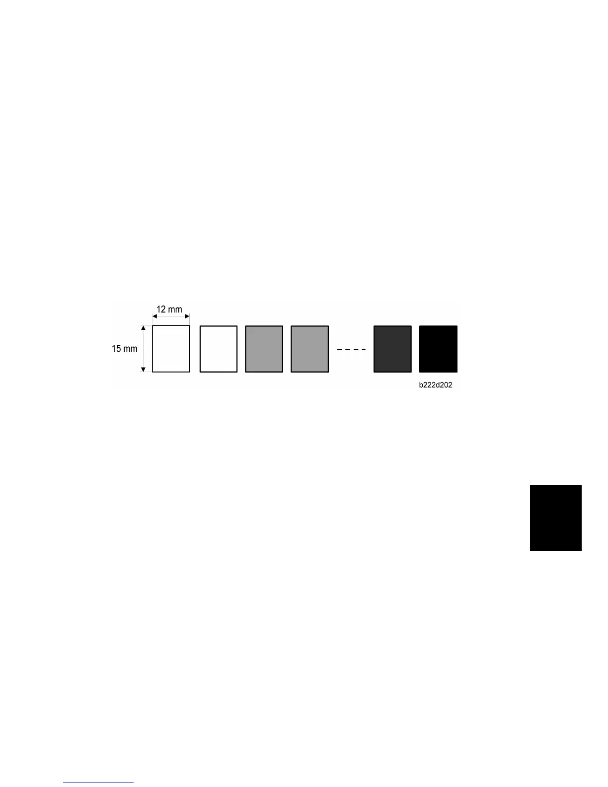
Second, the machine makes the grade patterns (see the diagram). This 10-grade pattern is
made in black, yellow, cyan, and magenta (40 squares in total).
The machine first makes the first five grades for each color (the first 20 squares), and
then the second five grades for each color (the remaining 20 squares).
The patterns are made by changing the development bias and charge roller voltage. The
difference between development bias and charge roller voltage is always the same. But,
the development potential changes for each pattern.
The development potential is the difference between the development bias and the
charge remaining on the drum where the laser writes a black area. The development
bias changes for each grade, and the charge on black areas of the image is always the
same, so the development potential also changes.
Step 3: Sensor Pattern Detection
The ID sensor measures the light reflected from each grade of the pattern, to detect the
densities of each grade. This data goes to memory.
Step 4: Toner Amount Calculation
The machine calculates the amount of toner on the transfer belt that is required to make

 Loading...