Home
Ricoh
All in One Printer
G179
Ricoh G179 User Manual
4
of 1
of 1 rating
682 pages
Give review
Manual
Specs
To Next Page
To Next Page
To Previous Page
To Previous Page
Loading...
Electrical Component
s
G179 3-66
SM
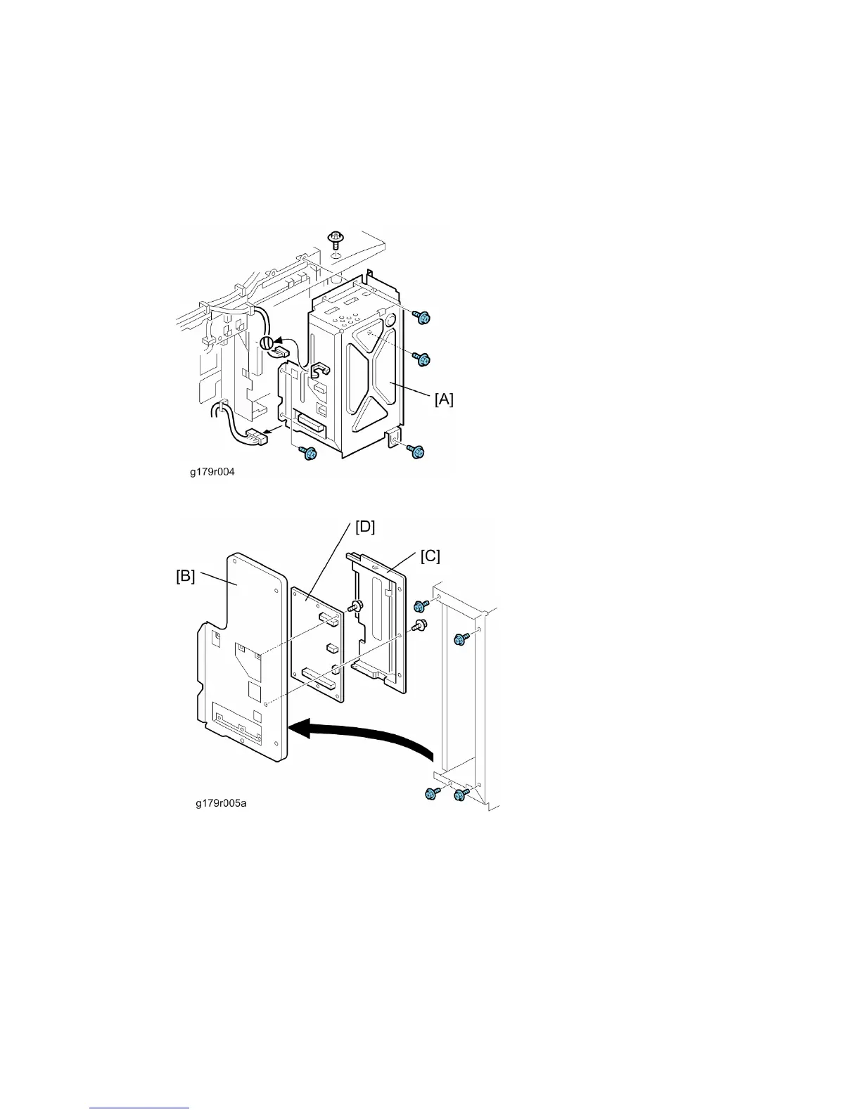
3.14.4 MOTHER
BOARD
1.
Rear cover (
Rear Cover)
2.
Controller unit (
Controller Unit)
3.
Controller box [A] (
x 7,
=
x 1,
x 2)
4.
Controller box right cover [B] (
x 4)
5.
Mother board bracket [C] (
x 1)
6.
Mother board [D] (
x 6)
CÓPIA NÃO CONTROLADA
CÓPIA NÃO CONTROLADA
153
155
Table of Contents
Table of Contents
13
Default Chapter
1
Service Manual
1
Read this First
27
Safety Notices
27
Laser Safety
28
Symbols and Abbreviations
29
Installation
33
Installation Requirements
35
Environment
35
Machine Level
36
Minimum Space Requirements
36
Power Requirements
37
Main Machine Installation
38
Installation Overview
38
Power Socket for Peripheral
39
Installation Flowchart
40
Moving the Machine
40
Transporting the Machine
40
Lct 2000-Sheet (D352)
41
Accessory Check
41
Installation Procedure
41
1200-Sheet Lct (D353)
44
Component Check
44
Installation Procedure
44
Bridge Unit (D386)
47
Component Check
47
Installation Procedure
47
3000-Sheet Finisher (B805)
51
Accessory Check
51
Installation Procedure
52
Support Tray Installation
55
Punch Unit (B702)
56
Component Check
56
Installation Procedure
57
Output Jogger Unit (B703)
61
Accessories
61
Installation
61
1000-Sheet Finisher (B408)
63
Accessory Check
63
Installation Procedure
64
Tray Heater
66
Installation Procedure
66
Tray Heater (Optional Paper Feed Unit)
68
Component Check
68
For Installing the Tray Heater in the D351 (Two-Tray Paper Feed Unit)
69
Installation Procedure
69
For Installing the Tray Heater in the D352 (LCT)
72
Preventive Maintenance
77
Service Maintenance Parts - Mainframe
79
Pm Parts Tables for Mainframe
79
Service Maintenance Parts - Options
84
Pm Parts Tables for Options
84
Troubleshooting
167
Service Tables
217
Detailed Section Descriptions
394
Replacement and Adjustment
87
General Cautions
89
Laser Unit
89
Used Toner
89
Lubricants
90
Special Tools
90
Special Tools and Lubricants
90
Exterior Covers
91
Front Door, Upper and Lower Inner Cover
91
Left Cover
91
Lower Inner Cover
92
Rear Cover
92
Right Rear Cover
92
Upper Inner Cover
92
Operation Panel
93
Top Right and Top Rear Cover
93
Output Tray
94
Paper Exit Cover
94
Caution Decal Locations
96
Laser Unit
96
Polygon Mirror Motor
97
Laser Synchronization Detector
98
Ld Unit
98
Laser Beam Pitch Adjustment
99
Drum
101
Pcdu
101
Pcdu (Photoconductor and Development Unit)
101
Reinstallation
101
Pick-Off Pawl Position Adjustment
105
Pick-Off Pawls
105
Charge Roller and Cleaning Roller
106
Drum Cleaning Blade 1
107
Drum Cleaning Blade 2
107
Re-Installation
107
ID Sensor
108
Re-Installation
108
Development
109
Development Filter
109
Development Roller
109
Developer
110
Td Sensor
112
Transfer
113
Transfer Belt Unit
113
Transfer Belt
115
Toner Overflow Sensor
117
Transfer Belt Cleaning Blade
117
Paper Feed
118
Paper Feed Unit
118
Tray 1 and Tray 2
118
Pick-Up, Feed and Separation Rollers
119
Tray 1 and Tray 2
119
Tray Lift Motor
119
Registration Sensor
120
Reinstall the Registration Sensor
122
Fusing
123
Fusing Unit
123
Brake Pad
124
Web Roller Unit
124
Web Holder Roller and Web Rollers
125
Installing a New Web Holder Roller
127
Installing New Web Rollers
127
Pressure Roller Cleaning Roller
128
Thermostat
129
Hot Roller Strippers
130
Thermistor
130
Fusing Lamps
131
Hot Roller and Pressure Roller
132
Fusing Exit, Paper Overflow, and Paper Exit Sensors
133
Paper Exit
133
Paper Exit Sensor
133
Paper Exit Unit
133
Fusing Exit Sensor
134
Junction Jam Sensor
134
Paper Exit Motor
134
Paper Overflow Sensor
134
Duplex
135
Duplex Unit
135
Duplex Door Sensor
137
Duplex Entrance Sensor
137
Right Door Cover
137
Duplex Exit Sensor
138
Duplex Inverter Motor
140
Duplex/By-Pass Motor
140
By-Pass
143
By-Pass Paper Size Sensor
143
When Reinstalling the By-Pass Paper Size Sensor
143
By-Pass Paper End Sensor
144
By-Pass Pick-Up, Feed and Separation Roller, Torque Limiter
144
By-Pass Feed Clutch
145
Development Paddle Motor
146
Drive Area
146
Paper Feed Clutch
146
Tray 1 and Tray 2
146
Drum Motor
147
Transfer/Development Motor
147
Fusing Motor
148
Web Motor
148
Paper Feed Motor
149
Registration Motor
149
Transfer Belt Contact Motor
149
Toner Supply Motor
150
After Installing the New HDD Unit
151
Controller Unit
151
Electrical Components
151
Hdd Unit
151
Replacement Procedure
151
Controller Board
152
Replacement Procedure
152
After Installing the Controller Board
153
When Installing the New Controller Board
153
Mother Board
154
Bcu
155
Iob
155
When Installing a New IOB
155
High Voltage Power Supply Board
156
Psu
156
Controller Fan
157
Fusing Exhaust Fan
157
When Installing the Fusing Exhaust Fan
157
When Installing the Controller Fan
158
Print Adjustments
159
Registration - Leading Edge/Side-To-Side
159
Blank Margin
160
Main Scan Magnification
162
Parallelogram Image Adjustment
162
Troubleshooting
165
Sc Code Descriptions
167
Service Call Conditions
167
Sc Tables: Sc1Xx
169
Sc Tables: Sc2Xx
170
Sc Tables: Sc3Xx
172
Sc Tables: Sc4Xx
175
Sc Tables: Sc6Xx
186
Sc Tables: Sc7Xx
189
Sc Tables: Sc9Xx
206
Electrical Component Defects
208
Blown Fuse Conditions
213
Service Tables
215
General Notes
217
Service Program Mode Operation
217
To Set the Printer in the Service Mode
217
Accessing the Required Program
218
Exiting Service Mode
218
Inputting a Value or Setting for a Service Program
218
Service Program Mode Tables
219
Service Table Key
219
Bit Switch Programming
220
Controller Service Mode
221
Engine Sp1-XXX: Feed
224
Sp3-XXX: Process
254
Sp6-XXX: Peripherals
307
Input Check
349
Main Machine
349
Table 1: Paper Height Sensor
351
Table 2: Paper Size Switch
352
Table 3: Paper Size (By-Pass Table)
353
Output Check
359
Sheet Finisher
365
Test Pattern Printing
368
Using Sp Modes
368
Nip Band Width Check: Sp
369
Smc Print out Lists: Sp
369
Memory Clear: Sp
370
Reviewing the Module Statuses
372
Setting the Machine in Firmware Update Mode
372
Updating the Firmware
372
How to Update a Module
373
Firmware Update Error
374
Handling Firmware Update Errors
375
Printing the Self-Diagnosis Report
375
Recovery after Power Loss
375
Error Message Table
376
Downloading Nvram Data (Sp)
378
Nvram Data Upload/Download
378
Uploading Nvram Data (Sp)
378
Move Exec
379
Sd Card Appli Move
379
Use Caution When You Do the Sd Card Appli Move Procedure
379
Undo Exec
380
Self-Diagnostic Mode
381
Self-Diagnostic Mode at Power on
381
Self-Diagnostic Test Flow
382
Executing Detailed Self-Diagnosis
383
Setting up "Save Debug Log
384
To Switch Debug Log on
384
Using Debug Log
384
To Select Events
385
To Select the Target for the Debug Log File
385
More about Debug Log
388
Retrieving the Debug Log from the Hdd
388
Sp5857-016: Make Hdd Logfile
388
Sp5857-017: Make Sd Log File
389
Dip Switches
390
I/O Board: Dip Sw
390
Detailed Section Descriptions
391
Paper Path
394
Drive Layout
395
Block Diagram
397
Board Structure
397
Image Transfer
401
Print Process
401
Laser Exposure
403
Auto Power Control (Apc)
404
Ld Safety Switches
404
Around the Drum
405
Drum Cleaning
406
Drive Mechanism
407
Drum Pawls
407
New Pcdu Unit Detection
408
New Unit Detection Mechanism
408
Drum Charge
410
Charge Roller Voltage Correction
411
Correction for Environmental Conditions
411
Correction for Paper Width and Thickness
412
Drum Charge Roller Cleaning
413
ID Sensor Pattern Production Timing
413
Developer Mixing
415
Correction for Paper Width and Thickness (By-Pass Tray Only)
416
Development Bias
416
Toner Bottle Replenishment Mechanism
418
Toner Supply
418
Sensor Control Mode
419
Toner Density Control
419
Toner Supply Mechanism
419
Image Pixel Count Mode
420
Toner End
420
Toner Near End
420
Toner Near End/End Detection
420
Toner End Recovery
421
Toner Supply with Abnormal Sensors
421
Drum Cleaning and Toner Recycling
422
Toner Recycling
423
Paper Feed Drive
425
Paper Lift
426
Tray Lock Mechanism
427
Paper Size Detection – Trays 1 and
428
Paper End Detection – Trays 1 and
429
By-Pass Tray
431
By-Pass Paper Separation
432
By-Pass Paper Size Detection
432
Duplex Unit
433
Duplex Drive
434
Inverter Mechanism
435
Duplex Operation
436
Belt Drive Mechanism
439
Transfer Belt Unit Contact Mechanism
439
Image Transfer and Paper Separation
440
Transfer Belt Charge
441
Currents Applied to Leading Edge, Image Areas - By-Pass Feed
442
Transfer Belt Cleaning Mechanism
443
Image Fusing
444
Fusing Drive
445
Pressure Release Mechanism
445
Fusing Entrance Guide Shift Mechanism
446
Pressure Roller Cleaning
446
Hot Roller Cleaning
447
Web Drive
447
Web Near-End
447
Hot Roller Stripper Cleaning
448
St Cleaning Mode
448
Web End
448
Nd Cleaning Mode
449
Rd Cleaning Mode
449
Sp Settings for Post-Job Cleaning
449
Fusing Temperature Control
451
Cpm down System
453
Fusing Idling Temperature
453
Overheat Protection
454
Paper Feed Waiting Mode
454
Junction Gate Mechanism
456
To Duplex Unit
457
Exit Guide Plate and De-Curler Rollers
458
Energy Saver Modes
459
Specifications
461
General Specifications
463
Printer Drivers
466
Software Accessories
466
Utility Software
466
Na Model
468
Supported Paper Sizes
468
Eu/ Asia Model
470
Sheet Booklet Finisher
474
Machine Configuration
477
Lct 2000-Sheet
479
Optional Equipment
479
Two-Tray Paper Feed Unit
479
Bridge Unit
480
Lct 1200-Sheet
480
Lower Tray
481
Punch Unit for 3000-Sheet Finisher
484
1000-Sheet Finisher B408
487
1 Replacement and Adjustment
489
Main Pcb
489
Stapler Unit
490
Motors
491
Shift Motor
491
Stapler Motor
491
Lower Transport Motor
492
Upper Transport Motor and Exit Motor
492
Motors and Sensors
493
Preparation
493
Stack Height Sensor
494
Stapler Tray Paper Sensor
494
Lower Tray Lift Motor
495
Stack Feed-Out Motor
495
2 Troubleshooting
496
Jam Detection
496
3 Service Tables
497
Dip Switch Settings
497
4 Detailed Descriptions
498
General Layout
498
Electrical Component Layout
499
Electrical Component Description
501
Drive Layout
503
Junction Gates
504
Sort/Stack Mode
504
Staple Mode
504
Upper Tray Mode
504
Upper Tray
505
Lower Tray Up/Down Mechanisms
506
Paper Shift Mechanism
507
Jogger Unit Paper Positioning Mechanism
508
Exit Guide Plate
509
Stapler Mechanism
510
Stapler Unit Movement Mechanism
511
Paper Feed-Out Mechanism
512
Booklet Finisher Sr3020/ Finisher Sr3030 B804/B805
515
1 Replacement and Adjustment
519
Covers
519
Exterior Covers
519
Upper Tray, End Fence
520
Main Unit
521
Upper Tray Limit Sensor, Limit Switch
521
Positioning Roller
522
Proof Tray Exit Sensor
522
Exit Guide Plate, Upper Tray Exit Sensor
523
Upper Tray Height Sensors 1, 2
523
Proof Tray Full Sensor
524
Finisher Entrance Sensor
525
Pre-Stack Tray Exit Sensor
525
Stapler Unit
526
Corner Stapler
526
Positioning Roller
527
Fold Unit
528
Fold Unit Entrance Sensor
530
Fold Unit Exit Sensor
530
Stack Present Sensor
531
Folding Horizontal Skew Adjustment (for B804 Only)
532
Fold Vertical Skew Adjustment (for B804 Only)
535
Booklet Stapler Unit
537
Booklet Stapler
537
Booklet Stapler Motor
537
2 Detailed Section Descriptions
540
Component Layout
540
General Layout
540
Electrical Components
542
Summary of Electrical Components
546
Drive Layout
556
Junction Gates
558
Proof Mode
558
Shift Mode
558
Staple Mode
559
Pre-Stacking
560
Tray Movement Mechanism
562
Upper Tray
562
Lower Tray (B804 Only)
564
Corner Stapling
567
Stacking and Jogging
567
Stapler Movement
568
Corner Stapling
570
Booklet Pressure Mechanism
571
Booklet Stapling (B804 Only)
571
Booklet Stapling and Folding
572
Booklet Stapling and Folding Mechanisms
578
Feed out
581
Upper Tray Output
581
Feed out Stacking
582
Overview of Operation
583
Punch Unit B702 (for B804/B805)
583
Punch Mechanisms
585
Punch Unit Movement
586
Punch Selection and Firing
587
Punch Hopper Mechanism
588
Finisher Jam Detection
590
Paper Feed Unit Pb3040 (D351)
595
1 Replacement and Adjustment
599
Rear Cover
599
Motors and Clutches
600
Lift Motors
600
Upper and Lower Paper Feed Clutches
600
Paper Feed Motor
601
Main Board
602
Lift, Paper End, and Relay Sensors
603
Paper Feed Unit
604
Pick-Up, Paper Feed and Separation Rollers
605
2 Details
606
Component Layout
606
Mechanical Component Layout
606
Electrical Component Layout
607
Paper Feed
608
Paper Size Detection
609
Reverse Roller and Pick-Up Roller Release
611
Paper Height and End Detection
612
Paper Height Detection
612
Paper End and Bottom Plate
613
Paper Lift
614
Lcit Pb3050 (D352)
617
1 Replacement and Adjustment
621
Left and Right Tray
621
Sensors
622
End Fence Hp Sensor/Paper End Sensor 2
622
Paper Height Sensors on the Paper Storage Side
622
Changing the Tray Size
623
Main Board
624
Clutches
625
Paper Feed Clutch
625
Stack Transport Clutch
625
Paper Feed Unit
626
Motors
627
Tray Lift Motor
627
Tray Motor
628
Pick-Up, Feed and Separation Rollers
629
Paper Feed, Paper End, Lift and Relay Sensors
630
Paper Feed
631
2 Details
632
Component Layout
632
Mechanical Component Layout
632
Electrical Component Layout
633
Electrical Component Descriptions
634
Separation Roller and Pick-Up Roller Release
636
Tray Lift
637
Paper Amount Detection
638
Paper End Detection (Paper Feed Side)
639
Paper Stack Transport
640
1200-Sheet Lcit Rt3000(D353)
643
1 Replacement and Adjustment
647
Covers
647
Rear Cover
647
Right Door
647
Front and Top Covers
648
Paper Feed
649
Pick-Up, Paper Feed and Separation Rollers
649
Drive
650
Paper Feed Clutch
650
Paper Feed Motor
650
Tray Lift Motor
651
Electrical Components
652
Lct Set Switches
652
Main Board
652
Down Switch
653
Paper Feed, Paper End, Tray Lift and Relay Sensors
653
Stack Sensor
655
Side Fence Position Change
656
2 Details
657
Component Layout
657
Electrical Component Descriptions
658
Electrical Component Layout
658
Drive Layout
661
Paper Feed
662
Paper Feed Mechanism
662
Tray Lift Mechanism
663
Tray Lifting Conditions
663
Paper Height and End Detection
664
Bridge Unit Control Board
673
Replacement and Adjustment
673
Bridge Unit Drive Motor
674
Tray Exit Sensor
675
Relay Sensor
676
Details
677
Mechanical Component Layout
677
Drive Layout
678
Electrical Component Layout
679
Electrical Component Description
680
Junction Gate Mechanism
681
4
Based on 1 rating
Ask a question
Give review
Questions and Answers:
Need help?
Do you have a question about the Ricoh G179 and is the answer not in the manual?
Ask a question
Ricoh G179 Specifications
General
Brand
Ricoh
Model
G179
Category
All in One Printer
Language
English
Related product manuals
Ricoh G104
601 pages
Ricoh G133
993 pages
Ricoh G147
496 pages
Ricoh G065
278 pages
Ricoh GR-C1
1207 pages
Ricoh Gestetner 5430
128 pages
Ricoh Gestetner MP 4001
81 pages
Ricoh MP C3004
2154 pages
Ricoh Pro 8300S
188 pages
Ricoh aficio 1013F
384 pages
Ricoh Aficio MP C3500
236 pages
Ricoh Aficio MP C2800
260 pages

 Loading...