Laser Unit
SM 3-11 G179
Replacement
Adjustment
To avoid damaging the LD board, hold it securely when disconnecting the
connectors. Hold the laser unit casing.
5. After replacing the LD board, do the "Laser Beam Pitch Adjustment" (described in the
following section). Keep the lower inner cover removed before doing this adjustment
because you need to adjust the adjustor screw [D] on the LD unit with a screwdriver.
Laser Beam Pitch Adjustment
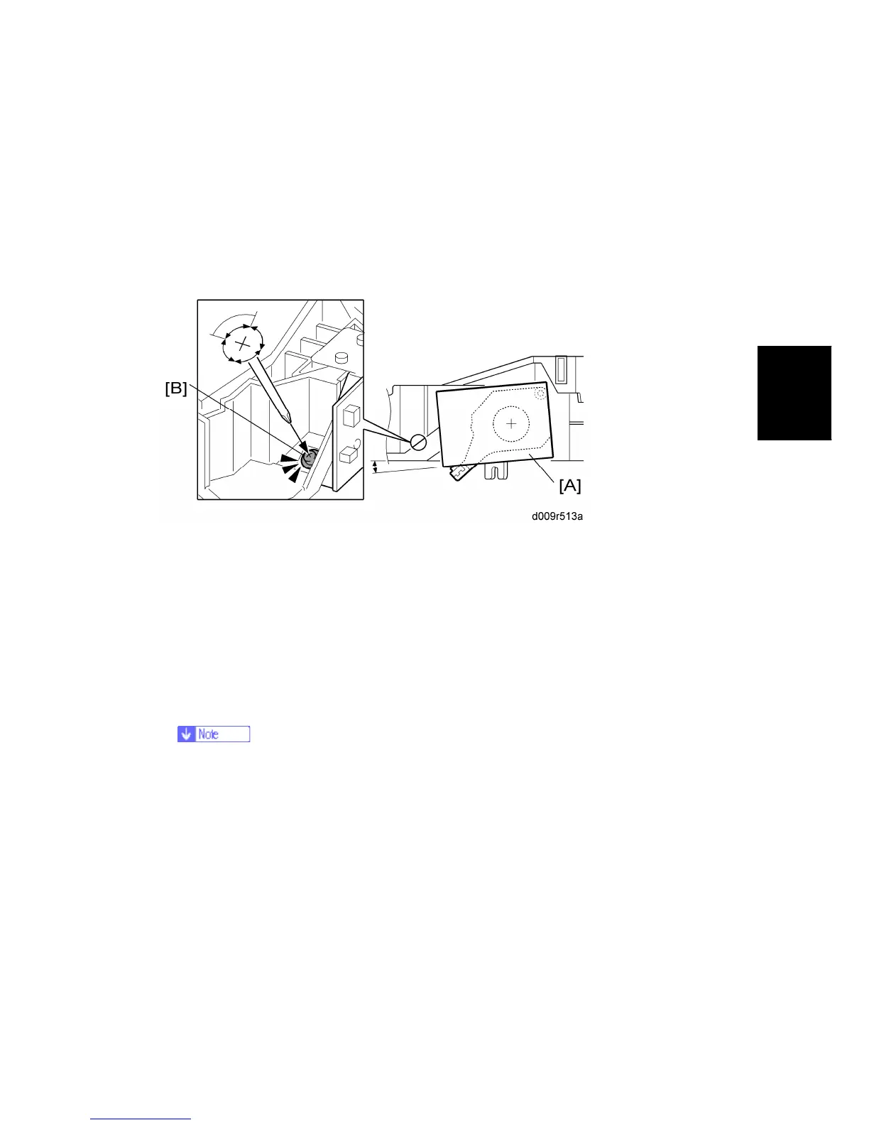
1. Install a (new) LD unit [A] with the left side of the LD unit being lower than the right side.
(This makes this adjustment easier.)
2. Print the test pattern "Hound.s Tooth Check (Horizontal)" (No. 16 in SP2109-001).
3. Check if the vertical stripes appear on the second pattern (counted from the leading
edge) of the printout.
Correct: No vertical stripes appear (see the sample following this procedure.)
Wrong: Vertical stripes appear (see the sample following this procedure.)
4. Turn the adjustor screw [B] by 90 degrees clockwise (counterclockwise).
If the image of the printout is getting worse, try reverse rotation (clockwise ↔
counterclockwise)
5. Print the test pattern and check it out.
6. Try steps 2 to 4 again until you get an image with no vertical stripes.
7. Reassemble the machine after completing this adjustment.

 Loading...