Component Layout
D351 8 SM
2. DETAILS
2.1 COMPONENT LAYOUT
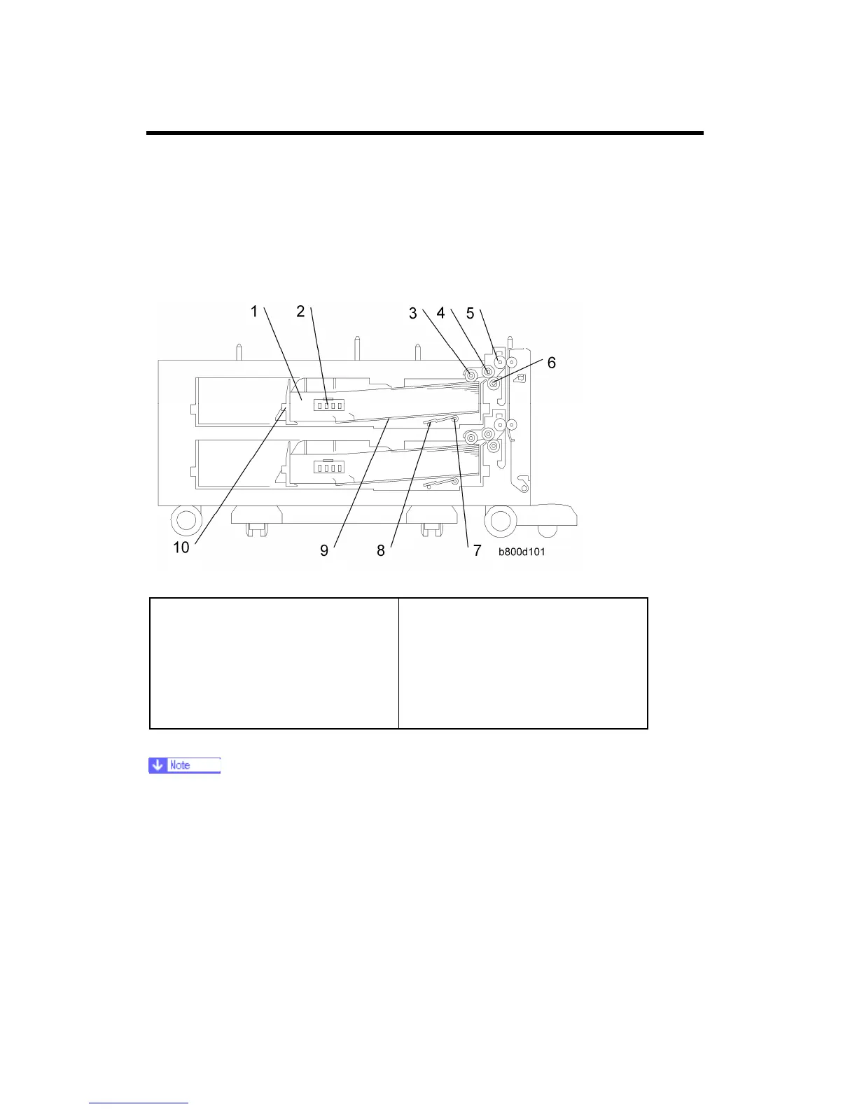
2.1.1 MECHANICAL COMPONENT LAYOUT
1. Upper tray
2. Paper size switch: Upper tray
3. Pick-up roller: Upper tray
4. Paper feed roller
5. Vertical transport roller
6. Separation roller
7. Tray lift arm
8. Lift arm shaft
9. Bottom plate
10. End plate
Listed above are the components of tray 1 (upper tray). Tray 2 (lower tray) has the
same components as tray 1.

 Loading...