Laser Unit
SM 3-9 G179
Replacement
Adjustment
2. Front door [A] (pins x 2)
3. Upper inner cover [B] ( x 2)
4. Glass cap [C]
5. Shield glass [D]
6. Lower inner cover [E] ( x 2)
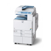
7. Laser unit connectors [E] ( x 3, = x 1)
Do not disconnect the harnesses on the LD board [F] unless the LD unit has to
be replaced. This board is precisely adjusted in the factory.
8. Laser unit [G] ( x 2)
When sliding out the laser unit, do not hold the LD board. Hold the laser unit.
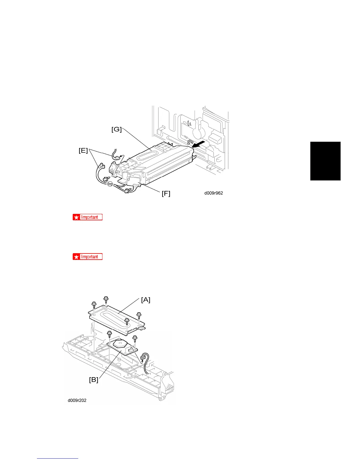
3.4.3 POLYGON MIRROR MOTOR

 Loading...