EasyManua.ls Logo

Ricoh G179 User Manual

Ricoh G179
682 pages
To Next Page IconTo Next Page
To Previous Page IconTo Previous Page
Page #220 background imageLoading...
Page #220 background image
Service Program Mode Operation
G179 5-4 SM
5.1.4 BIT SWITCH PROGRAMMING
Do not change the bit switches unless you are told to do this by the manufacturer.
1. Start the SP mode. Select the “Service” menu with "#/%" keys.
2. Press the "OK" key three times.
3. To select a bit switch, press the "'/(" keys.
4. Push the OK key.
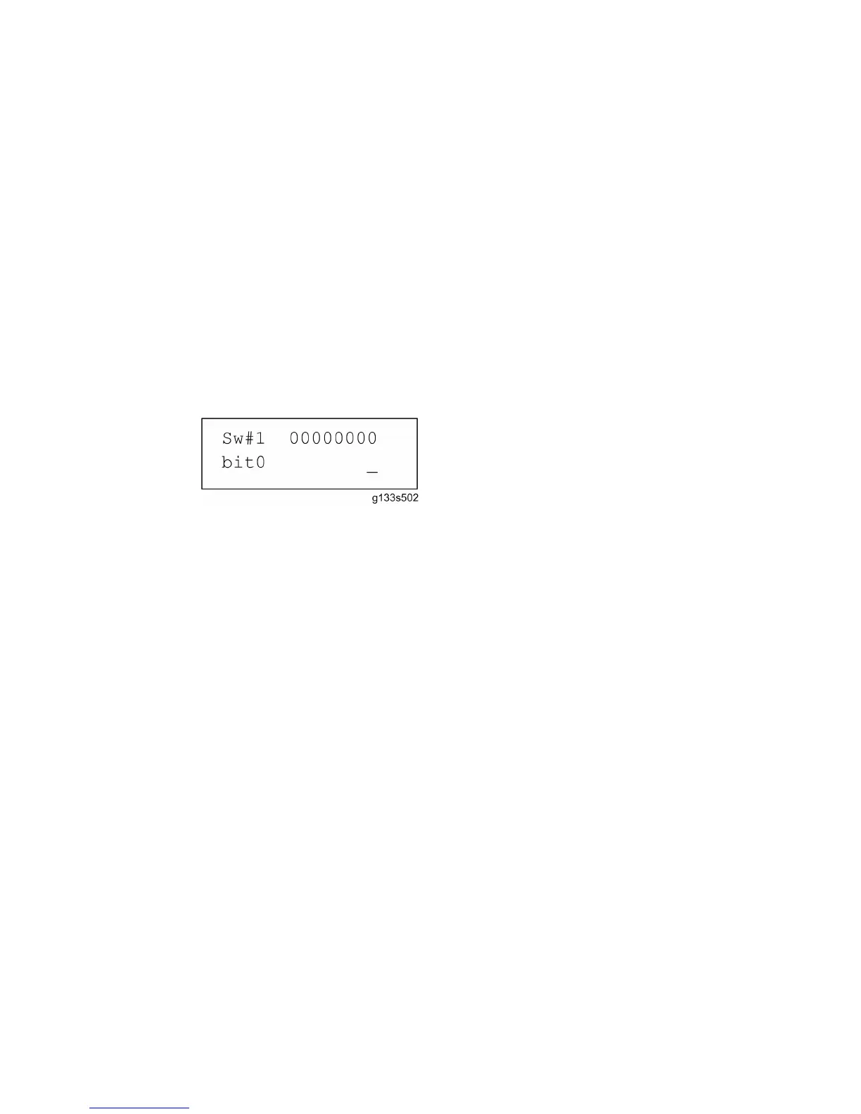
5. Set the value with these keys:
[Left] [Right]: Moves the cursor to one of the adjacent bits.
[Up] [Down]: Changes a bit between "0" and "1".
[Escape]: Goes out of the program without saving changes.
[OK]: Goes out of the program and saves changes.
6. Push the "Escape" key one or more times until the menu “SP mode (Service)” is
shown.
7. Select “End” and push the OK key.
CÓPIA NÃO CONTROLADA

Table of Contents

Question and Answer IconNeed help?

Do you have a question about the Ricoh G179 and is the answer not in the manual?

Ricoh G179 Specifications

General IconGeneral
FunctionsPrint, Copy, Scan, Fax
ConnectivityUSB 2.0, Ethernet
Product TypeAll-in-One Printer
Print TechnologyLaser
Print ResolutionUp to 1200 x 1200 dpi
Duplex PrintingAutomatic
Paper Capacity250 sheets
Scanner TypeFlatbed, ADF
Operating Systems SupportedWindows, macOS

Summary

1. INSTALLATION

1.1 INSTALLATION REQUIREMENTS

Specifies environmental, power, and space requirements for machine installation.

3. REPLACEMENT AND ADJUSTMENT

3.1 GENERAL CAUTIONS

Provides critical safety and handling cautions before replacement or adjustment.

3.4 LASER UNIT

Covers safety precautions and procedures for replacing the laser unit.

3.5 PCDU

Explains the replacement and re-installation procedures for the PCDU.

3.6 DEVELOPMENT

Details procedures for replacing the development filter, roller, and developer.

3.7 TRANSFER

Covers replacement procedures for the transfer belt unit and related components.

3.8 PAPER FEED

Provides steps for replacing paper feed unit components like rollers and motors.

3.9 FUSING

Details procedures for replacing fusing unit components like rollers and heaters.

3.10 PAPER EXIT

Explains replacement procedures for paper exit unit components and sensors.

3.11 DUPLEX

Covers replacement procedures for duplex unit components like motors and sensors.

3.12 BY-PASS

Details replacement procedures for by-pass paper size and end sensors.

3.13 DRIVE AREA

Covers replacement procedures for various drive motors and clutches.

3.14 ELECTRICAL COMPONENTS

Explains replacement procedures for electrical components like controller and power boards.

4. TROUBLESHOOTING

4.1 SERVICE CALL CONDITIONS

Explains the different levels of service call conditions and their reset procedures.

4.13 ELECTRICAL COMPONENT DEFECTS

Lists common electrical component defects, their CN, conditions, and symptoms.

4.14 BLOWN FUSE CONDITIONS

Details blown fuse conditions, ratings, and symptoms at power on.

5. SERVICE TABLES

5.27 UPDATING THE FIRMWARE

Provides detailed steps for updating the machine's firmware via SD card.

5.30 SELF-DIAGNOSTIC MODE

Describes the self-diagnostic mode at power-on and test flows.

1000-SHEET FINISHER B408

2. TROUBLESHOOTING

Lists jam detection modes, staple status, and content for troubleshooting.

BOOKLET FINISHER SR3020/ FINISHER SR3030 B804/B805

PAPER FEED UNIT PB3040 D351

LCIT PB3050 D352

BRIDGE UNIT BU3030 D386

1. REPLACEMENT AND ADJUSTMENT

Covers replacement of control board, drive motor, tray exit, and relay sensors.

Related product manuals