Image Fusing
G179 6-54 SM
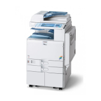
6.13.4 FUSING ENTRANCE GUIDE SHIFT MECHANISM
The entrance guide [A] has two holes on each side to adjust for paper thickness to prevent
creasing. Normally, the left screw hole [B] on each side is used.
For thin paper, use screw holes [C] to move the entrance guide to the left. This setting
allows more direct access to the gap between the hot and pressure rollers, and prevents
thin paper from buckling against the hot roller which can cause blurring at the leading edge
of the output.
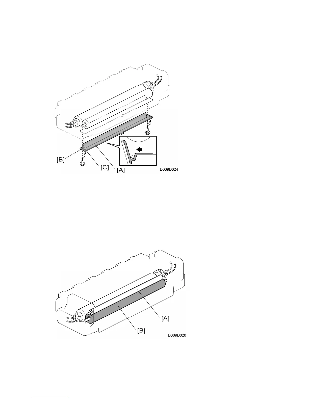
6.13.5 PRESSURE ROLLER CLEANING
The pressure roller cleaning [A], in constant contact with the pressure roller [B], collects
toner and paper dust from the surface of the pressure roller.

 Loading...